Input device using sensors mounted on finger tips

a technology of input device and finger tip, which is applied in the direction of instruments, computing, electric digital data processing, etc., can solve the problems of difficult to accurately recognize the motion of fingers by image processing, the position restriction of the input device, etc., and achieve the effect of reducing the size and weight of the information processing device and less positional restrictions

Inactive Publication Date: 2010-09-16
IWATA HARUYUKI
View PDF12 Cites 49 Cited by
  • Summary
  • Abstract
  • Description
  • Claims
  • Application Information

AI Technical Summary

Benefits of technology

[0009]Since the keyboard, which has been difficult to miniaturize, can be omitted, various information processing devices can be further reduced in size and weight.
[0010]If the input device is used in combination with a head mounted display (HMD) (13) or the like, wearable computing can be achieved.
[0011]The input device has less positional restrictions. For example, a sick person can perform an input operation in any posture in bed. Thus, the input device is expected to be advantageous in terms of welfare.
[0012]If a user carries the input device according to claim 1 or 2 incorporating a fingerprint or vascular recognition...

Problems solved by technology

However, as with the conventional keyboards, the keyboard input device has restrictions as to the position during operation, such as fingers of the hands have to be placed on the keyb...

Method used


Image

  • Input device using sensors mounted on finger tips
  • Input device using sensors mounted on finger tips
  • Input device using sensors mounted on finger tips

Examples


embodiment 1

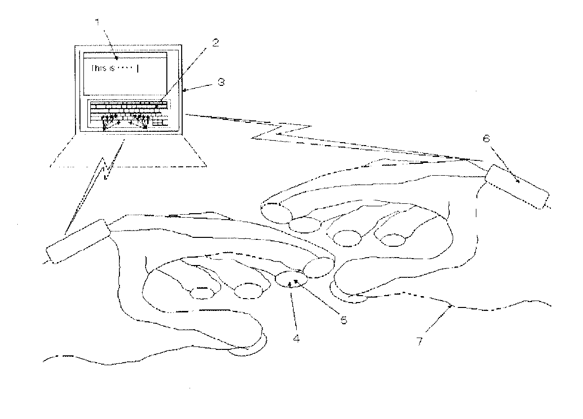
[0020]FIG. 1 is a diagram showing the whole of an input device according to the present invention in a case where the input device is implemented as a virtual keyboard input device.

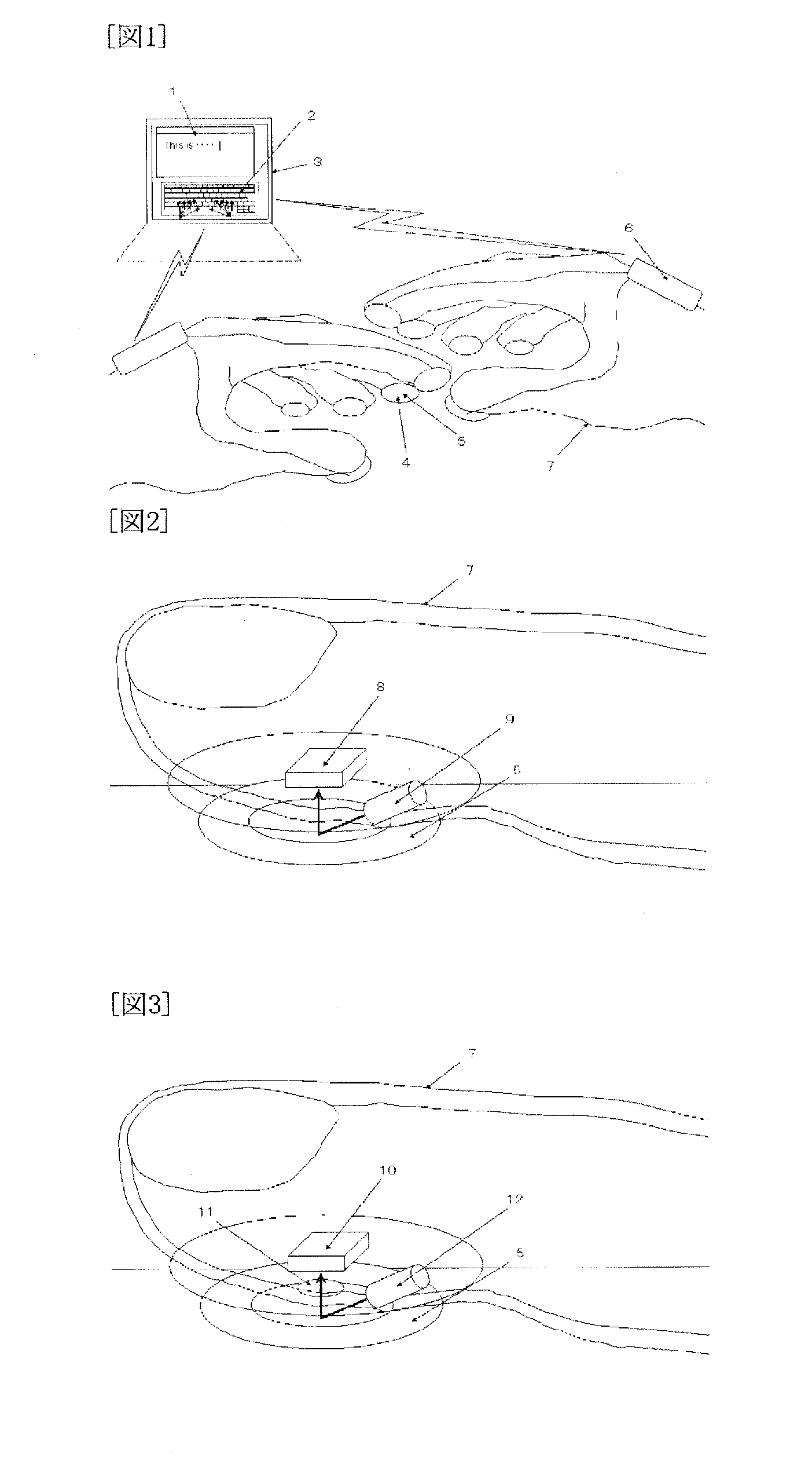
[0021]FIG. 2 is a diagram for illustrating a case where a finger-tip part according to the present invention is composed of a laser sensor (8). The motions of the finger tips are detected by recognizing the texture or irregularity of a desk, clothes or the like based on the same principle as a laser mouse composed of the laser sensor (8) and a laser diode (9), and information about the motions is transmitted to a personal computer (PC) or the like. More specifically, images of what lies beneath the finger tips are regularly stored, the images for the same finger tip before and after motion are compared to calculate the amount and direction of motion of the finger tip, and the calculation result is transmitted to the personal computer (PC) or the like. When a finger tip is pressed against a desk or the lik...

embodiment 2

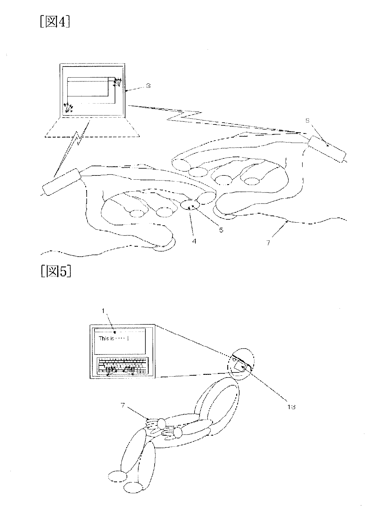
[0023]FIG. 4 is a diagram showing the whole of the input device according to the present invention in a case where the input device is used to achieve click and drag operations.


PUM


Abstract

In order to allow key input without operation of a keyboard or allow click and drag operations by finger tips of the hands, the present invention is primarily characterized in that a user wears a glove (7) (including a glove that covers only finger tips), which has a motion detection sensor (4) (based on the same principle as a laser mouse or an optical mouse) and a tactile sensor (5) (a conductive rubber, a piezoelectric element or the like) mounted on each finger-tip part thereof, on each hand (like mounting a small laser mouse or optical mouse on each finger tip), motion information about each finger tip is transmitted to an information processing device, such as a personal computer (PC), a PDA and a cellular phone, the position of each finger tip is displayed on a virtual keyboard (2) shown on a display (3) of the information processing device, and the tactile sensor (5) detects the pressure on a finger tip when the finger tip is pressed against an arbitrary object, such as a desk, thereby allowing input of a key corresponding to the finger tip pressed against the arbitrary object.

Description

TECHNICAL FIELD[0001]The present invention relates to an input device using sensors mounted on finger tips that allows key input without using a conventional keyboard or allows a click or drag operation via finger tips of the hands.BACKGROUND ART[0002]A conventional virtual keyboard input device has an infrared sensor installed on top of a portable computer, such as a cellular phone, and recognizes the motions of fingers based on image processing (see the Patent Document 1, for example).[0003]However, as with the conventional keyboards, the keyboard input device has restrictions as to the position during operation, such as fingers of the hands have to be placed on the keyboard. In addition, depending on the environmental condition (the background, the illumination or the like), it is difficult to accurately recognize the motions of fingers by image processing.[0004]Patent Document 1: Japanese Patent Laid-Open No. 2005-258482DISCLOSURE OF THE INVENTIONProblems to be Solved by the Inv...

Claims


Application Information

Patent Timeline
IPC IPC(8): G09G5/00G06F3/033G06F3/0354
CPCG06F3/014G06F3/04886
Inventor IWATA, HARUYUKI
Owner IWATA HARUYUKI
Why Eureka
Try Eureka