
Display of video with motion

a technology of video and motion, applied in the field of video image display, can solve the problems of blurred ball images, inability to adjust the image, so as to achieve the effect of reducing motion blur

Active Publication Date: 2010-09-16
INTELLECTUAL VENTURES FUND 83 LLC
View PDF22 Cites 45 Cited by
  • Summary
  • Abstract
  • Description
  • Claims
  • Application Information

AI Technical Summary

Benefits of technology

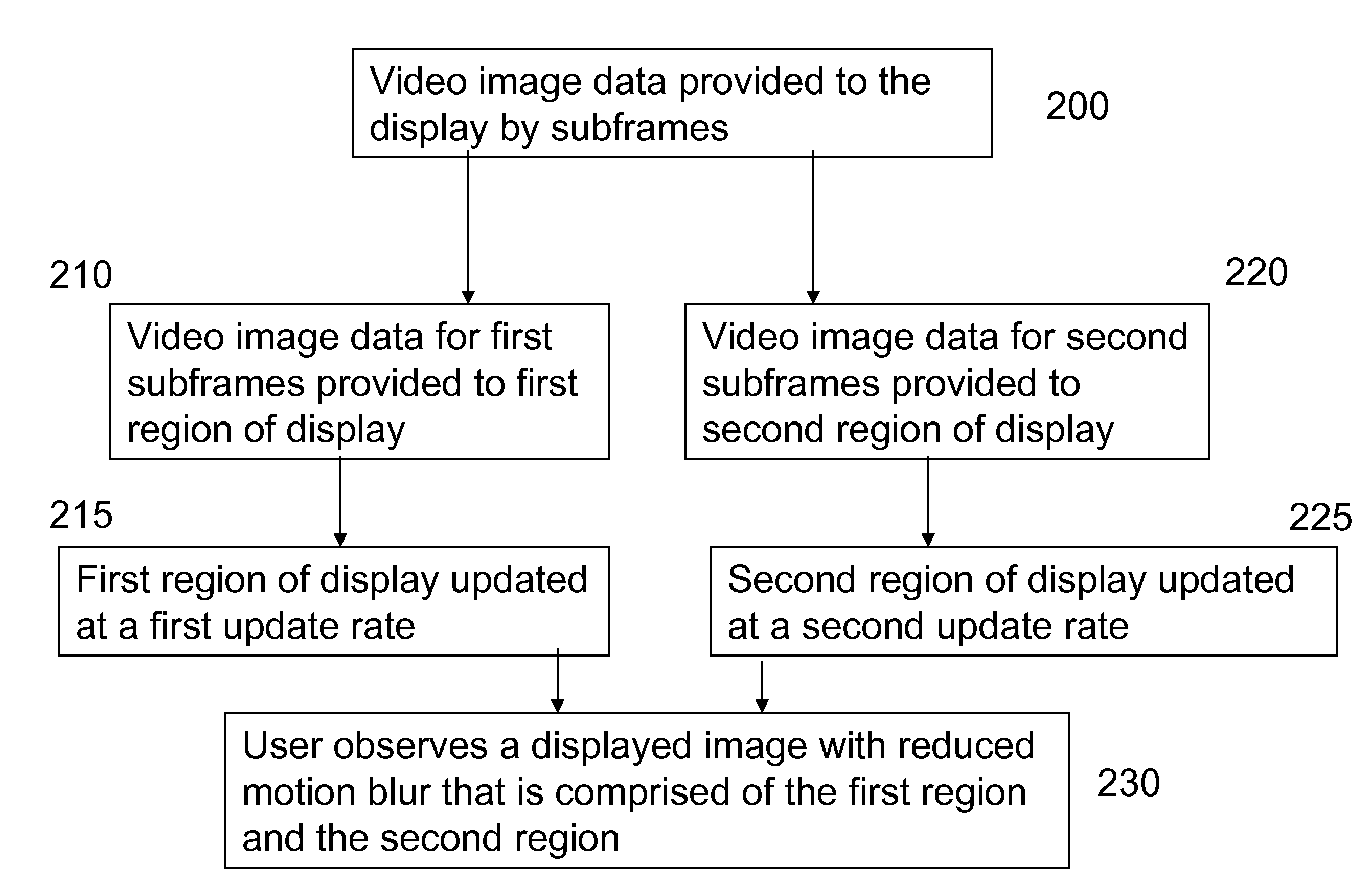
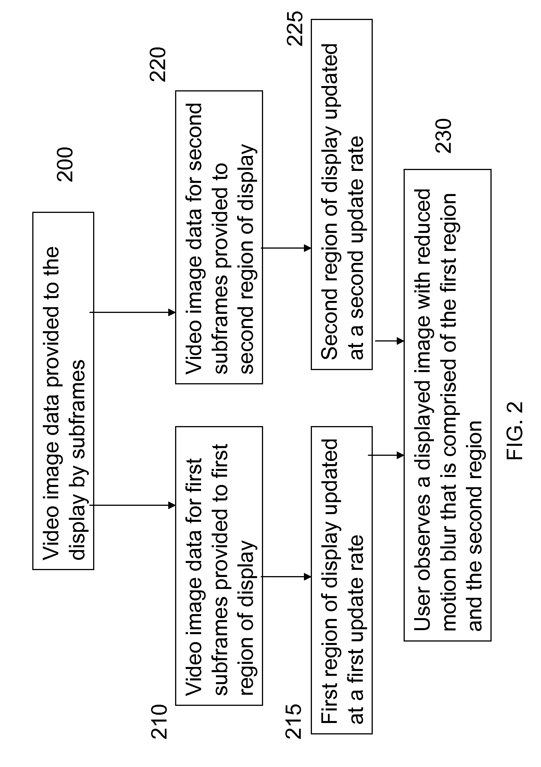
[0014](b) selectively providing the first and second subframes to corresponding regions in the display, and providing the first region of the display with a first update rate and the second region of the display with a second update rate, wherein the first update rate is greater than the second update rate, so that the displayed image has reduced motion blur.

Problems solved by technology

However, when rapid motion is present in a scene, such as a ball being thrown in a sporting event, the image of the ball can be noticeably blurred even at 60 fps.
However, as the frame rate is increased, the amount of image data increases proportionately, which can result in data rates too high for data storage, image processing or data transmission bandwidth in imaging systems such as a consumer video camera, a digital camera or a cell phone camera.
The update rate is limited by the response time of the display.
However, limitations in the drive electronics of EL displays, the image transmission systems and the image processing system within the video capture devices such as consumer video cameras, a digital camera or a cell phone camera, do not permit update rates above approximately 30 Hz to be supported at higher resolutions.
If the capture systems supported very high frame rate with high resolution video capture, such video would require large amounts of bandwidth for transmission and special electronic drives for the display.
Doubling the rate of such drivers from 60 Hz to 120 Hz can be expensive.
Furthermore, in displays such as OLED displays, which typically have a high capacitance and have drive lines with a significant resistance, accurately updating information at 120 Hz and maintaining the full bit depth of the display can present a significant challenge.
Further, upconversion to 120 fps does not recognize the problem that significant image blur can be introduced during motion capture, and this motion blur is not reduced through these schemes.
Since this video is captured at this rate, it has likely undergone motion blur during capture and this blurring can make the estimation of motion difficult.
Therefore, the resulting video will contain artifacts due to errors in estimation of the rate of motion.

Method used


Image

  • Display of video with motion
  • Display of video with motion
  • Display of video with motion

Examples


Embodiment Construction

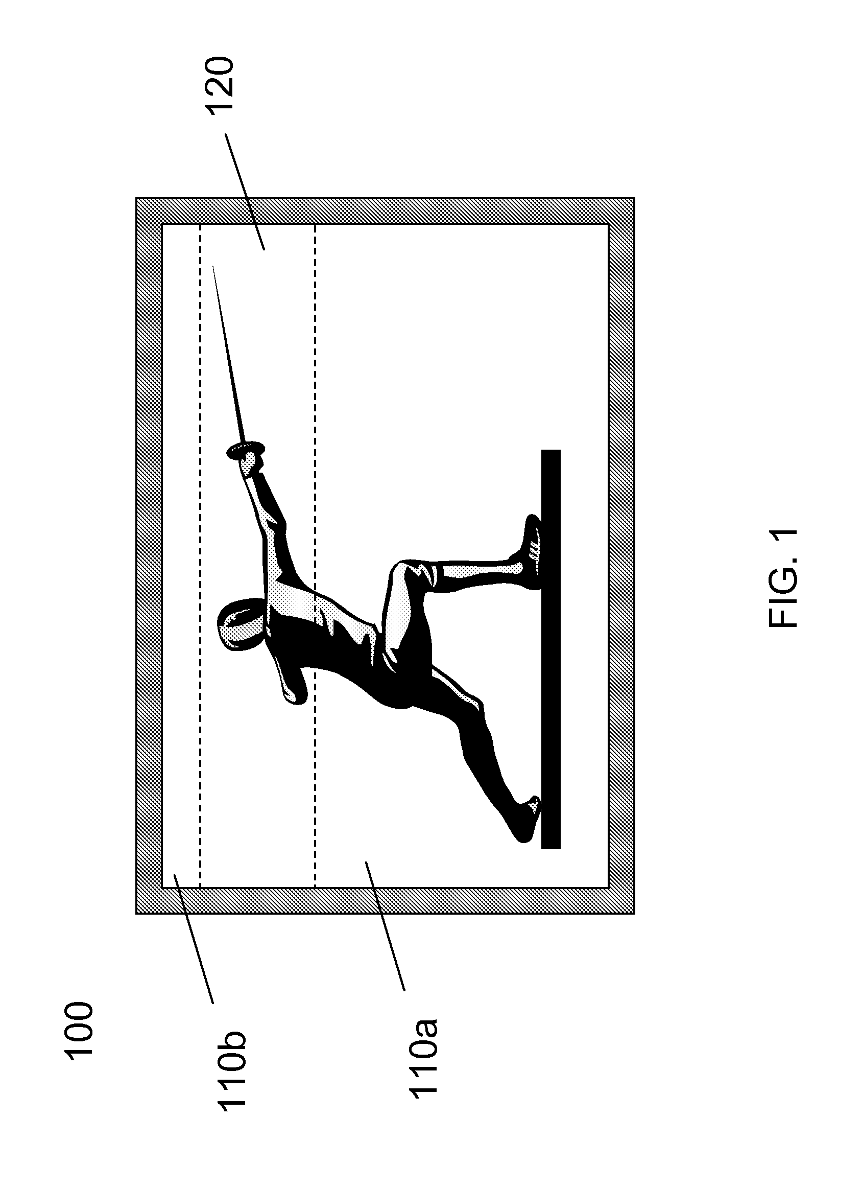
[0030]The invention provides a method to reduce motion blur in a displayed video image by providing an increased rate of image information to the regions of the display that are associated with rapid motion in the image. FIG. 1 shows an illustration of a display 100 showing an image of a person fencing wherein the fencer's arm and the foil are moving rapidly and as a result, those regions of the displayed video image are blurred. In an embodiment of the invention, a video signal of the scene is provided to the display. This video signal has first subframes that have a first input rate I1 and second subframes that have a second input rate I2. The input rates are measured in Hz. First and second subframe input times J1, J2, measured in seconds, are then defined as:

J1=1 / I1; J2=1 / I2.

[0031]The first subframes provide information corresponding to a first region of the display, which corresponds to a region for displaying fast motion, for example, corresponding to the first region 120 of t...


PUM


Abstract

A method of displaying a video of a scene on a display with reduced motion blur includes: providing the video of a scene having first subframes that have a first input rate and second subframes that have a second input rate, wherein the first subframes correspond to a first region of the display and the second subframes correspond to a second region of the display; and selectively providing the first and second subframes to corresponding regions in the display, and providing the first region of the display with a first update rate and the second region of the display with a second update rate, wherein the first update rate is greater than the second update rate, so that the displayed image has reduced motion blur.

Description

CROSS-REFERENCE TO RELATED APPLICATIONS[0001]Reference is made to commonly-assigned U.S. patent application Ser. No. ______ filed ______ entitled “Capture Of Video With Motion” to Border et al., the disclosure of which is incorporated herein.FIELD OF THE INVENTION[0002]The invention pertains to the display of video images. More specifically the invention pertains to an improved method for display of video images where rapid motion is present.BACKGROUND OF THE INVENTION[0003]Digital display of videos of scenes is a useful and commonly-practiced technique. Videos typically include a series of individual frames at a selected frame rate, e.g. 24 frames per second (fps), and each frame represents light accumulated for a selected exposure time, e.g. 41.7 ms (= 1 / 24 sec.). Each frame comprises a two-dimensional array of individual pixels.[0004]Scenes, and thus videos of scenes, can contain global motion or local motion. Global motion refers to relative motion between an image capture devic...

Claims


Application Information

Patent Timeline
IPC IPC(8): H04N9/77H04N5/14G09G3/28
CPCG09G3/2022G09G3/3225G09G2300/0876G09G2310/0267H04N5/14G09G2320/0261G09G2320/10G09G2320/106G09G2340/0435G09G2310/04
Inventor WHITE, CHRISTOPHER J.MILLER, MICHAEL E.BORDER, JOHN N.
Owner INTELLECTUAL VENTURES FUND 83 LLC
Learn More