Rail system and x-ray imaging apparatus using the same

a technology of x-ray imaging and rail system, which is applied in the direction of instruments, tubes with screens, image-conversion/image-amplification tubes, etc., can solve the problems of increasing installation costs, spatial limitations, and height of ceilings that must be able to vary, so as to reduce installation space and increase the space available for movement

Inactive Publication Date: 2010-09-16
MEDIEN INT
View PDF3 Cites 26 Cited by
  • Summary
  • Abstract
  • Description
  • Claims
  • Application Information

AI Technical Summary

Benefits of technology

[0011]Accordingly, the present invention has been made keeping in mind the above problems occurring in the prior art, and an object of the present invention is to provide a rail system for X-ray imaging apparatuses which can reduce installation space and thus increase space available for movement of a table on which a patient is lying for X-ray imaging, and an X-ray imaging apparatus using the rail system.

Problems solved by technology

However, in the conventional art, when installing a medical X-ray imaging apparatus, there is a spatial limitation.
However, there is a disadvantageous in that the height of the ceiling must range between from 2700 mm to 2800 mm.
Furthermore, the installation of the tube stand under the ceiling requires separate rail installation work that must tear off the ceiling.
The work of installing the tube stand on the rail provided under the ceiling increases the installation cost.
As well, in the case of medium and small hospitals having relatively small spaces, installation of the X-ray imaging apparatus may be impossible.
In addition, in this structure, the X-ray imaging apparatus cannot be implemented by using a single rail, and at least two rails are necessary.
This increases the installation cost.
Moreover, because two or more rails are provided on opposite sides of a table on which a patient lies for X-ray imaging, there is a problem in that movement of the table is greatly limited.

Method used


Image

  • Rail system and x-ray imaging apparatus using the same
  • Rail system and x-ray imaging apparatus using the same
  • Rail system and x-ray imaging apparatus using the same

Examples


first embodiment

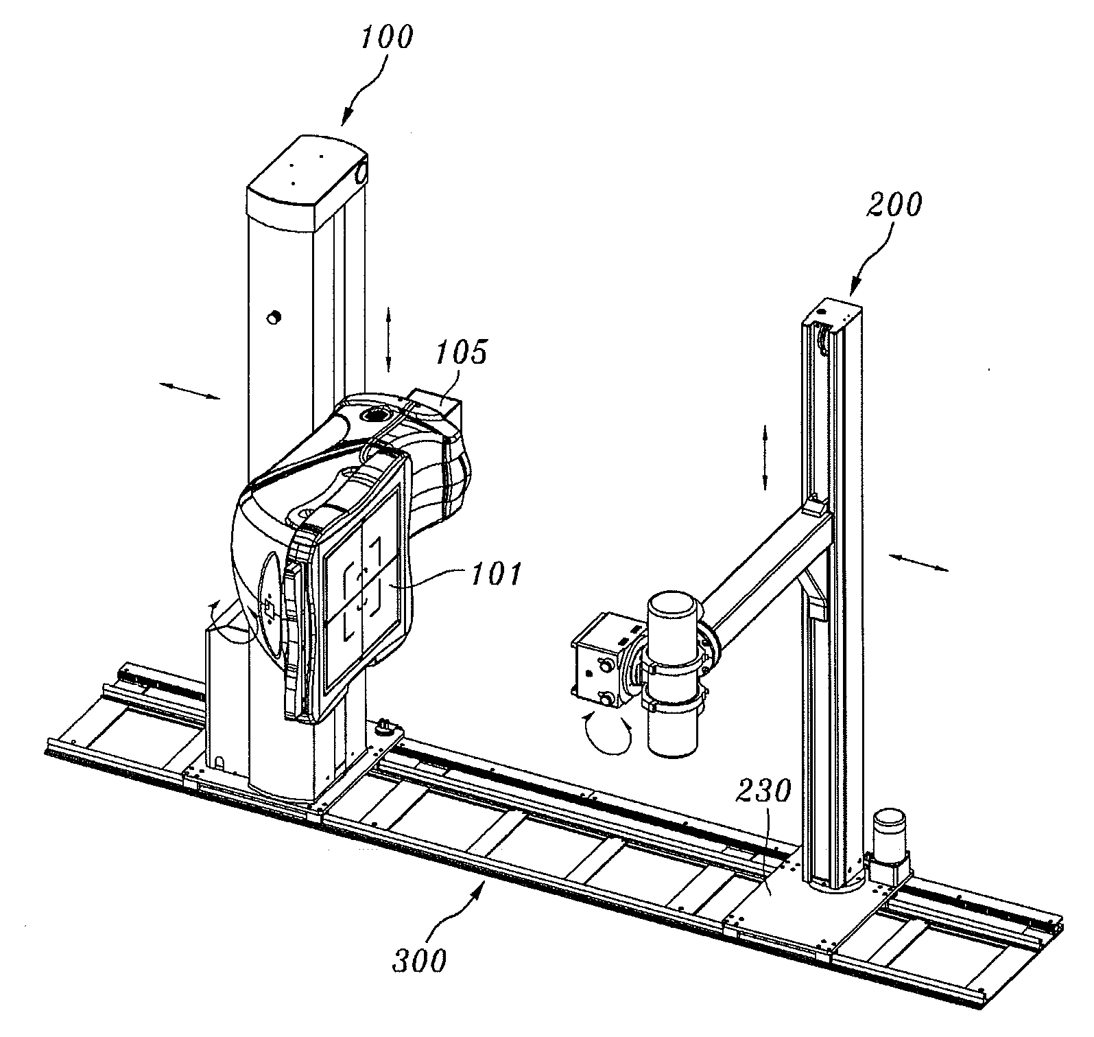
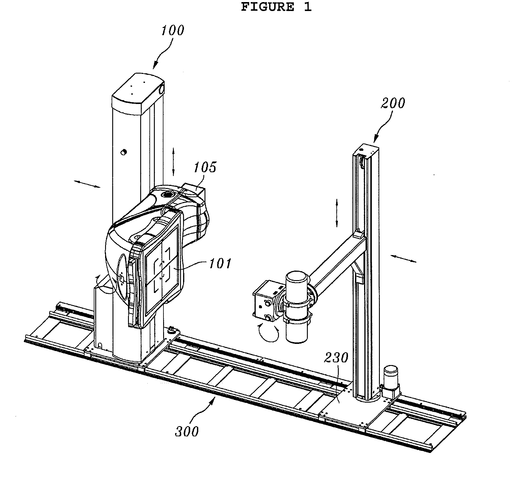
[0031]FIG. 1 is a perspective view illustrating a rail system, provided with a detector arm having a bent structure, and an X-ray imaging apparatus using the rail system, according to the present invention.

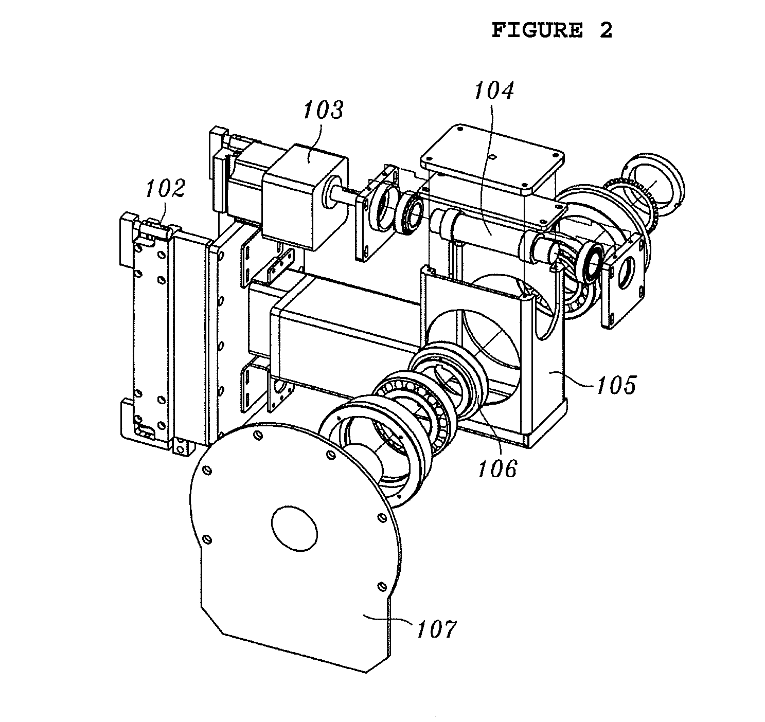
[0032]FIG. 2 is an exploded perspective view showing the detector arm of the rail system according to the first embodiment of the present invention.

[0033]FIG. 3 is a perspective view illustrating a detector stand of the rail system according to the first embodiment of the present invention.

[0034]FIG. 4 is an exploded perspective view illustrating a tube stand of the rail system according to the first embodiment of the present invention.

[0035]FIG. 5 is a perspective view illustrating a method of moving the X-ray imaging apparatus along the rail system according to the first embodiment of the present invention.

[0036]FIG. 6 is a perspective view showing the operation of the X-ray imaging apparatus according to the first embodiment of the present invention when imaging a patient who i...

second embodiment

[0105]FIG. 9 is a perspective view illustrating a rail system, provided with a tube arm having a bent structure, and an X-ray imaging apparatus using the rail system, according to the present invention.

[0106]In the following description of the rail system and the X-ray imaging apparatus according to the second embodiment of the present invention, the description pertaining to the same elements as those of the rail system and the X-ray imaging apparatus according to the first embodiment will be skipped, and only elements different therefrom will be explained.

[0107]In the second embodiment, a detector arm 105 is provided on a front surface of a detector stand 115 so as to be movable upwards and downwards.

[0108]The tube arm 206 having the bent structure is coupled to the tube stand 210 so as to be movable upwards and downwards such that the distal end of the tube arm 206 faces a detecting unit 100.

[0109]The operation of the rail system, provided with the tube arm 206 having the bent st...

third embodiment

[0121]FIG. 10 is a perspective view illustrating a rail system, provided with two rails and a detector arm having a bent structure, and an X-ray imaging apparatus using the rail system, according to the present invention.

[0122]As shown in FIG. 10, a detecting unit 100 provided the detector arm 105 having the bent structure may be provided on a first rail 306a, and an X-ray generating unit 200 may be provided on a second rail 306b.

[0123]Alternatively, a detecting unit 100 may be provided on the first rail 306a, and an X-ray generating unit 200 provided with a tube arm 206 having a bent structure may be provided on the second rail 306b.

[0124]The operation of the rail system having the two rails and the X-ray imaging apparatus using this rail system according to the third embodiment of the present invention is the same as that of the rail system having the single rail and the X-ray imaging apparatus using this rail system according to the first or second embodiment of the present inv...


PUM


Abstract

Disclosed herein are a rail system and an X-ray imaging apparatus using the same. The rail system includes a rail unit, a detecting unit and an X-ray generating unit. The rail unit is provided on a support surface and extends for a predetermined length. The detecting unit is provided on the rail unit and includes a detector stand which is provided on the rail unit so as to be movable in the longitudinal direction of the rail unit, a detector arm which has a bent structure and is provided on a side surface of the detector stand so as to be movable upwards and downwards, and a detector which is rotatably coupled to the detector arm. The X-ray generating unit is provided on the rail unit at a position facing the detector and includes a tube stand which is provided on the rail unit so as to be movable in the longitudinal direction of the rail unit, a tube arm which is provided on the tube stand so as to be movable upwards and downwards, an X-ray tube which is coupled to the tube arm so as to be rotatable with respect to the tube arm, and a collimator which is fastened to the X-ray tube.

Description

[0001]This patent application claims the benefit of priority under 35 U.S.C. §119 from Korean Patent Application No. 10-2009-0020278 filed on Mar. 10, 2009, the contents of which are incorporated herein by reference.BACKGROUND OF THE INVENTION[0002]1. Field of the Invention[0003]The present invention relates generally to rail systems and X-ray imaging apparatuses using the same and, more particularly, to a rail system for medical X-ray imaging apparatuses which are used in hospitals in order to image patient's bodies, and an X-ray imaging apparatus using the rail system.[0004]2. Description of the Related Art[0005]As is well known to those skilled in the art, when high-speed electrons strike a solid target, electromagnetic waves having high penetration are produced. These electromagnetic waves are called X-rays.[0006]The discovery of the X-ray having deep penetration made it possible to observe the interior of a human body without opening up the body, thus greatly contributing to th...

Claims


Application Information

Patent Timeline
Patent Type & Authority Applications(United States)
IPC IPC(8): H05G1/02H01J31/50G03B42/02
CPCA61B6/447A61B6/588A61B6/4482A61B6/00
Inventor AHN, PAN SOON
Owner MEDIEN INT
Why Eureka
Try Eureka