Method For Displaying Recognition Result Obtained By Three-Dimensional Visual Sensor And Three-Dimensional Visual Sensor

a three-dimensional visual sensor and recognition result technology, applied in the field of three-dimensional visual sensors, can solve the problem that the shape of the three-dimensional model cannot be properly expressed, and achieve the effect of enhancing the user-friendliness of the three-dimensional visual sensor and easy confirmation of the recognition resul

Inactive Publication Date: 2010-09-16
ORMON CORP
View PDF30 Cites 33 Cited by
  • Summary
  • Abstract
  • Description
  • Claims
  • Application Information

AI Technical Summary

Benefits of technology

[0024]In the recognition result displaying method and the three-dimensional visual sensor to which the recognition result displaying method is adopted, the user can easily confirm the recognition result by the checking with the three-dimensional model through the three-dimensional display of the three-dimensional model, and the user-friendliness of the three-dimensional visual sensor is considerably enhanced.

Problems solved by technology

However, because only a simple numerical display is difficult to understand, there is a user demand to be able to easily confirm the recognition result and accuracy of the recognition result.
Therefore, when the perspective transformation of the image in which a height according to a Z-coordinate at a corresponding point of the original model is correlated to each point of the projection image of the three-dimensional model is performed from a direction distant from a direction orthogonal to the imaging surface, the projection image whose size varies depending on a difference of the Z-coordinate is directly projected to produce the image having a large deformation, and therefore the shape of the three-dimensional model cannot properly be expressed.

Method used


Image

  • Method For Displaying Recognition Result Obtained By Three-Dimensional Visual Sensor And Three-Dimensional Visual Sensor
  • Method For Displaying Recognition Result Obtained By Three-Dimensional Visual Sensor And Three-Dimensional Visual Sensor
  • Method For Displaying Recognition Result Obtained By Three-Dimensional Visual Sensor And Three-Dimensional Visual Sensor

Examples


Embodiment Construction

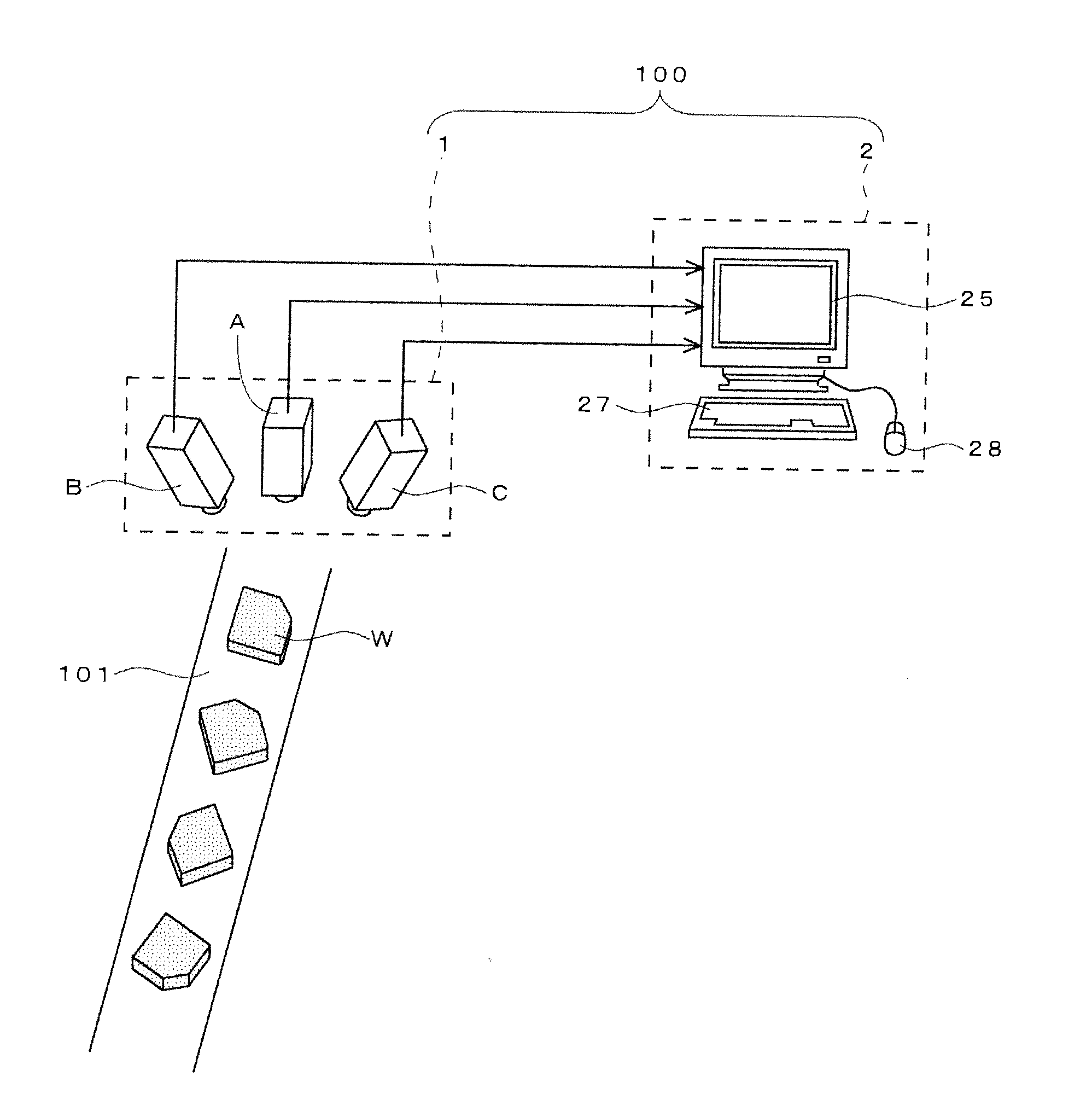
[0033]FIG. 1 illustrates an example in which a three-dimensional visual sensor 100 according to an embodiment of the invention is introduced to a production line of a factory.

[0034]The three-dimensional visual sensor 100 of the embodiment is used to recognize a position and an attitude of a workpiece W (morphology is simplified for the sake of convenience) conveyed by a conveying line 101 in order to assemble the workpiece W in a predetermined product. Information indicating recognition result is transmitted to a robot controller (not illustrated) of a robot (not illustrated) disposed downstream in the conveying line 101, and the information is used to control an operation of the robot.

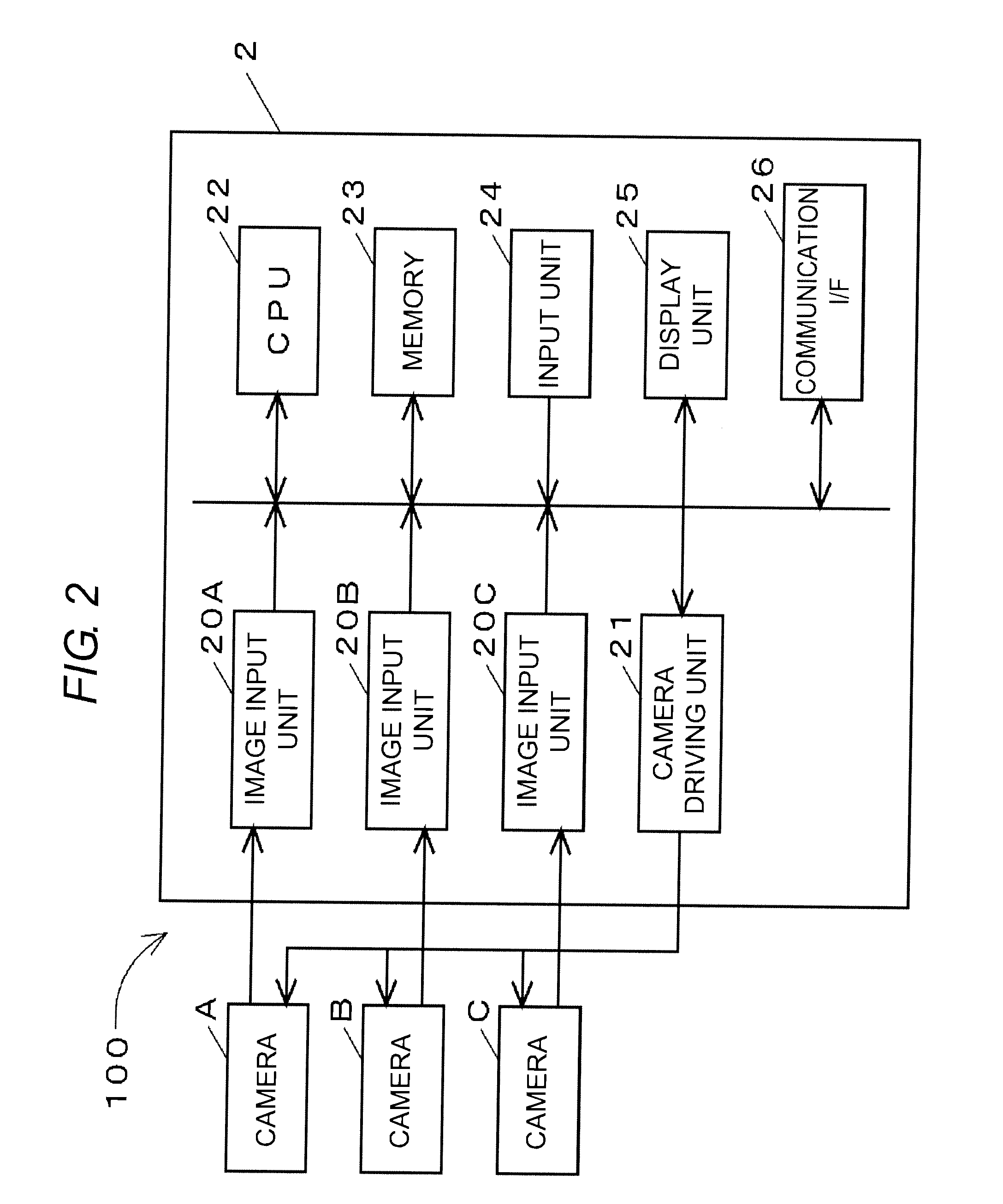
[0035]The three-dimensional visual sensor 100 includes a stereo camera 1 and a recognition processing device 2 that is disposed near the conveying line 101. The stereo camera 1 includes three cameras A, B, and C that are horizontally disposed above the conveying line 101. The central camera A is dispo...


PUM


Abstract

Display suitable to an actual three-dimensional model or a recognition-target object is performed when stereoscopic display of a three-dimensional model is performed while correlated to an image used in three-dimensional recognition processing. After a position and a rotation angle of a workpiece are recognized through recognition processing using the three-dimensional model, coordinate transformation of the three-dimensional model is performed based on the recognition result, and a post-coordinate-transformation Z-coordinate is corrected according to an angle (elevation angle f) formed between a direction of a line of sight and an imaging surface. Then perspective transformation of the post-correction three-dimensional model into a coordinate system of a camera of a processing object is performed, and a height according to a pre-correction Z-coordinate at a corresponding point of the pre-coordinate-transformation three-dimensional model is set to each point of a produced projection image. Projection processing is performed from a specified direction of a line of sight to a point group that is three-dimensionally distributed by the processing, thereby producing a stereoscopic image of the three-dimensional model.

Description

BACKGROUND OF THE INVENTION[0001]The present invention is based on Japanese Patent Application No. 2009-057430 filed with the Japan Patent Office on Mar. 11, 2009, the entire content of which is hereby incorporated by reference.1. TECHNICAL FIELD[0002]The present invention relates to a three-dimensional visual sensor that recognizes an object through three-dimensional measurement processing using a stereo camera, particularly to a technology for displaying recognition result.2. Related Art[0003]For example, when three-dimensional recognition processing is performed in order to cause a robot to grasp a component in a manufacturing scene, the three-dimensional information restored by the three-dimensional measurement of a stereo camera is checked with the previously registered three-dimensional model of the recognition-target object to recognize the position and attitude (specifically, a rotation angle with respect to three-dimensional model) of the recognition-target object (for exam...

Claims


Application Information

Patent Timeline
Patent Type & Authority Applications(United States)
IPC IPC(8): G06K9/00
CPCG06T7/0032G06T7/0046G06T2207/30164G06T2207/10012G06T15/20G06T7/344G06T7/75
Inventor FUJIEDA, SHIROTANENO, ATSUSHIYANO, HIROSHIIKEDA, YASUYUKI
Owner ORMON CORP
Why Eureka
Try Eureka