Toner cartridge capable of detecting residual amount of toner stored therein

a technology of toner cartridges and residual amounts, which is applied in the direction of electrographic process devices, instruments, optics, etc., can solve the problems of inability to accurately measure residual amounts of toner, complex apparatus structure, and large loss, so as to reduce non-linearity of detection means, improve cost and reliability of toner residuals, and sufficient detection sensitivity

Inactive Publication Date: 2010-09-16
ZHENG CHUNHUA
View PDF4 Cites 40 Cited by
  • Summary
  • Abstract
  • Description
  • Claims
  • Application Information

AI Technical Summary

Benefits of technology

[0014]Accordingly, the present invention has been made in an effort to solve the aforementioned problems occurring in the prior art, and it is an object of the present invention to provide a toner cartridge which can detect a change in the output period of a detection means due to a load torque of toner varying depending on a toner residual amount so as to measure the toner r

Problems solved by technology

Thus, in the case where a large amount of prints or a real-time printing is required, much loss occurs when printing is delayed due to consumption of the toner.
However, this method has a drawback in that it is possible to merely determine whether or not the level of the toner has dropped to below the predetermined level, but the residual amount of toner cannot be accurately measured.
However, the above U.S. patents entails a problem in that the driving characteristics of a mechanism is non-linear, resulting in unstable detection of a toner residual amount, two disks are used to detect the position of the padd

Method used


Image

  • Toner cartridge capable of detecting residual amount of toner stored therein
  • Toner cartridge capable of detecting residual amount of toner stored therein
  • Toner cartridge capable of detecting residual amount of toner stored therein

Examples


first embodiment

[0154]The auxiliary stirring means of the first embodiment includes an auxiliary stirring roller 132, a ratchet 690 and a pawl movement member 600. The ratchet 690 is fixed to one side of the auxiliary stirring roller 132 and rotates coaxially with the auxiliary stirring roller. The ratchet 690 rotates by the linear movement of a pawl in engagement with the ratchet. The pawl movement member 600 is connected to the stirring means and is linearly moved to drive the ratchet 690.

[0155]All the embodiments of the auxiliary stirring means feature that the auxiliary stirring means receives a driving force transmitted to the stirring means or a power from the same driving source as the driving force so that it is eventually driven in synchronization with the operation of the stirring means without needing an independent separate driving source.

[0156]The stirring means of the present invention, as described above, includes the first paddle, the second paddle and the elastic member for elastic...

second embodiment

[0160]Next, the auxiliary stirring means will be described hereinafter.

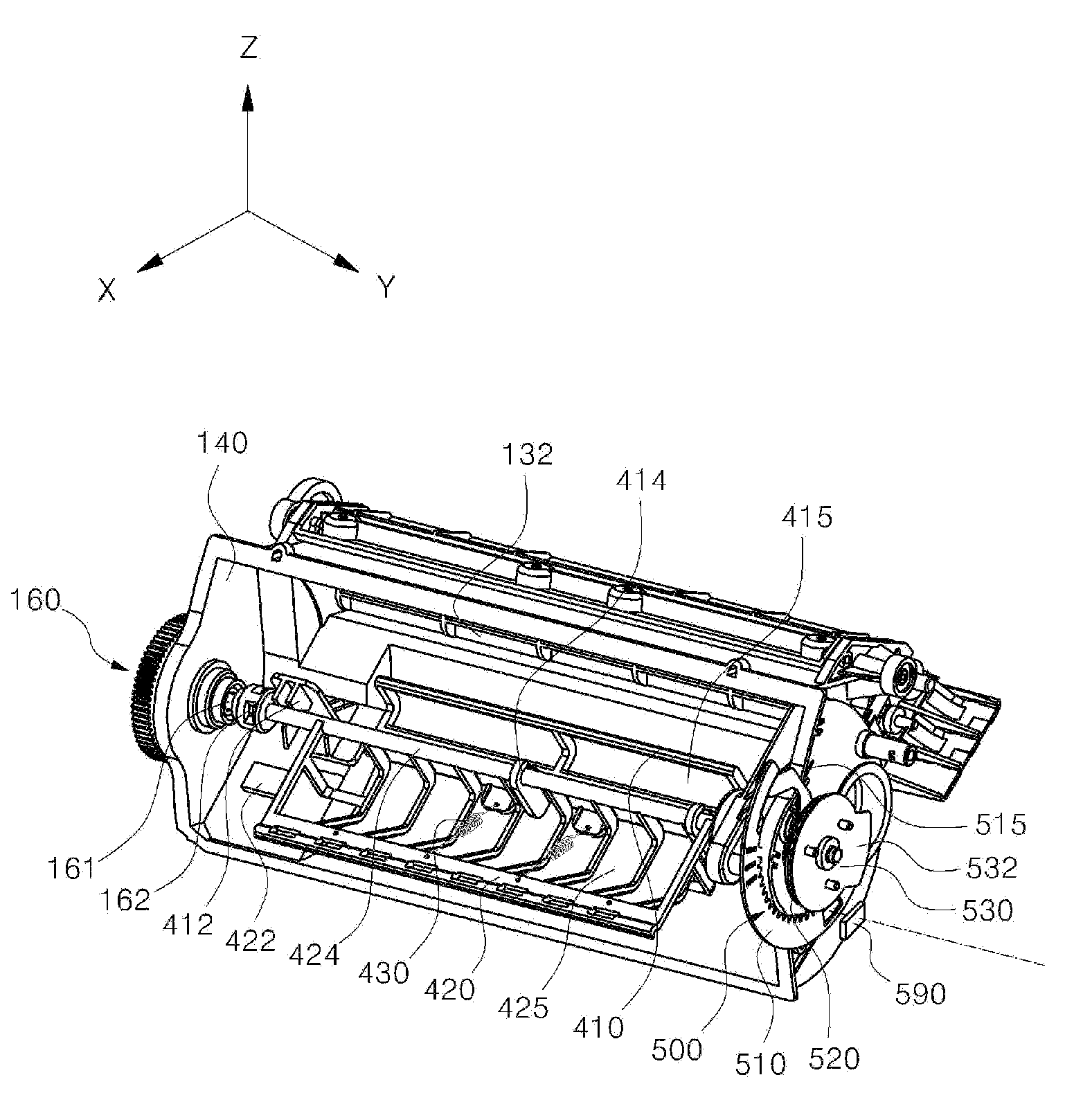
[0161]FIG. 32 is a perspective view illustrating the internal construction of a toner cartridge including an auxiliary stirring means of a second embodiment according to the present invention. FIGS. 33 and 34 are side cross-sectional views illustrating the operation of the auxiliary stirring means of the second embodiment according to the present invention.

[0162]The auxiliary stirring means of the second embodiment includes an auxiliary stirring roller 132, a roller gear 730, an intermittent gear 710 and a relay gear 720. The roller gear 730 is fixed to one side of the auxiliary stirring roller 132 and transmits a driving force to the auxiliary stirring roller 132. The relay gear 720 is provided between the roller gear 730 and the intermittent gear 710, and is used either in the case where the intermittent gear 710 and the roller 730 is spaced apart from each other to the extent that it is difficult to engage wit...

third embodiment

[0166]Subsequently, the auxiliary stirring means will be described hereinafter.

[0167]FIG. 35 is a perspective view illustrating the internal construction of a toner cartridge including an auxiliary stirring means of a third embodiment according to the present invention. FIGS. 36 to 39 are side cross-sectional views illustrating the operation of the auxiliary stirring means of the third embodiment according to the present invention.

[0168]The auxiliary stirring means of the third embodiment includes an auxiliary stirring roller 132, a first link 810, a second link 820 and an eccentric cam 830. A roller fixing portion 811 to which the rotation shaft of the auxiliary stirring roller 132 is fixed is provided at one side of the first link 810. When the first link 810 rotates about the roller fixing portion, the auxiliary stirring roller 132 rotates. A connecting rod 821 of the second link 820 is assembled to the other side of the first link 810 so that the first link 810 receives a drivin...


PUM


Abstract

The present invention provides a toner cartridge which comprises: a hopper for storing toner therein; a stirring means comprising a first paddle connected to a driving source and adapted to rotate in the hopper, and a second paddle connected to the first paddle by means of an elastic member, the stirring means being adapted to stir the toner in the hopper by the first paddle and the second paddle; and a detection means comprising an encoder having a first slit and a second slit formed thereon for transmitting light therethrough, the second slit having a width different from that of the first slit, an encoder gear connected to the second paddle for driving the encoder, and a sensor 590 mounted at a sensor reference position for outputting a first signal corresponding to the first slit and a second signal corresponding to the second slit, whereby the sensor detects a time delay of the second signal with respect to the first signal to measure the residual amount of the toner. The present invention also provides an electrophotographic image forming apparatus including the toner cartridge.

Description

BACKGROUND OF THE INVENTION[0001](a) Field of the Invention[0002]The present invention relates to a toner cartridge and an image forming apparatus including the same, and more particularly, to a toner cartridge capable of detecting the residual amount of toner stored therein, and an electrophotographic image forming apparatus including the same.[0003](b) Background Art[0004]An electrophotographic image forming apparatus is configured such that an electrostatic latent image corresponding to a desired image formed in advance on a photosensitive body is developed as a toner image every color and the developed image is transferred and fixed onto a printing medium such as a sheet of transfer paper to form the desired image. The toner is stored in a toner cartridge, and when the stored toner is used up, the spent toner cartridge is replaced with a new one.[0005]In this case, all the printing operations are stopped until the replacement of the toner cartridge is completed. Thus, in the cas...

Claims


Application Information

Patent Timeline
IPC IPC(8): G03G15/08
CPCG03G15/553G03G2215/066G03G15/0865G03G15/0856G03G15/0858G03G15/556
Inventor ZHENG, CHUNHUA
Owner ZHENG CHUNHUA
Why Eureka
Try Eureka