Electronic circuit for controlling a capacitive pressure sensor and capacitive pressure sensor system

a capacitive pressure sensor and electronic circuit technology, applied in the field of electronic circuits, can solve the problems of diaphragm biasing, large back volume, and higher production cos

Active Publication Date: 2011-03-10
NXP BV
View PDF7 Cites 36 Cited by
  • Summary
  • Abstract
  • Description
  • Claims
  • Application Information

AI Technical Summary

Benefits of technology

[0004]It is an object of the invention to provide an electronic circuit of the type defined in the opening paragraph and a capa

Problems solved by technology

However, large back volumes are very disadvantageous for micro-electro-mechanical-system (MEMS) based sensors, since they dramatically limit potential miniaturization and cause higher production costs.
The disadvantage of this method is that the diaphragm has to biased with the environmental pressure being about five orders of magnitudes higher than the average sound pressure for microphones.
Nevertheless, with this concept, the diaphragm is always in a critical state, since even smallest variations of the bias-voltage

Method used


Image

  • Electronic circuit for controlling a capacitive pressure sensor and capacitive pressure sensor system
  • Electronic circuit for controlling a capacitive pressure sensor and capacitive pressure sensor system

Examples


Embodiment Construction

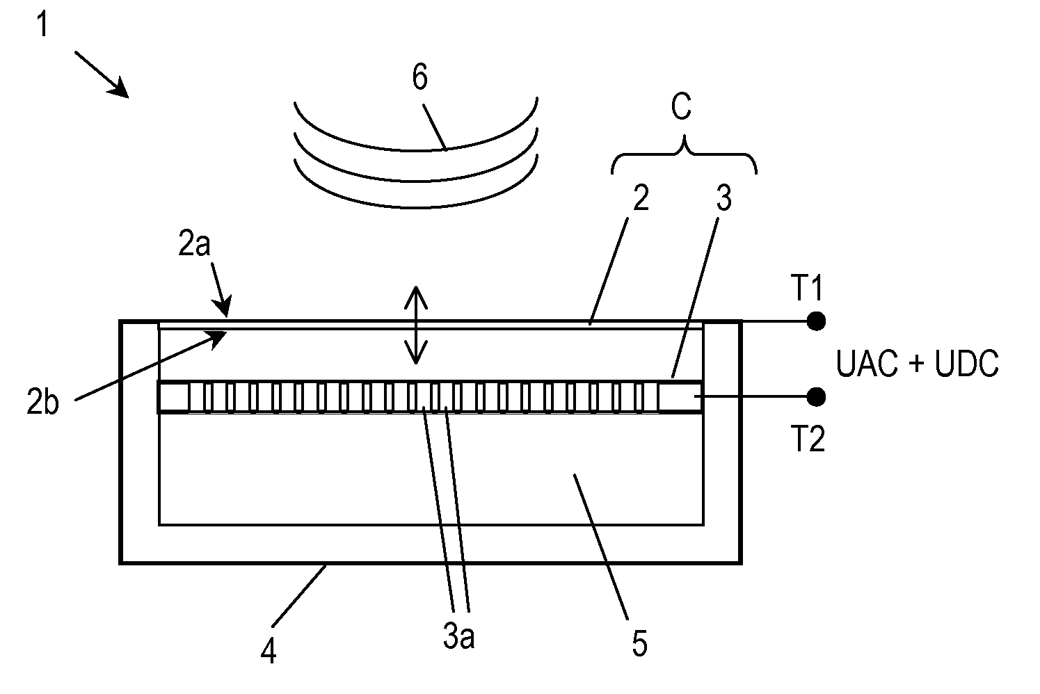
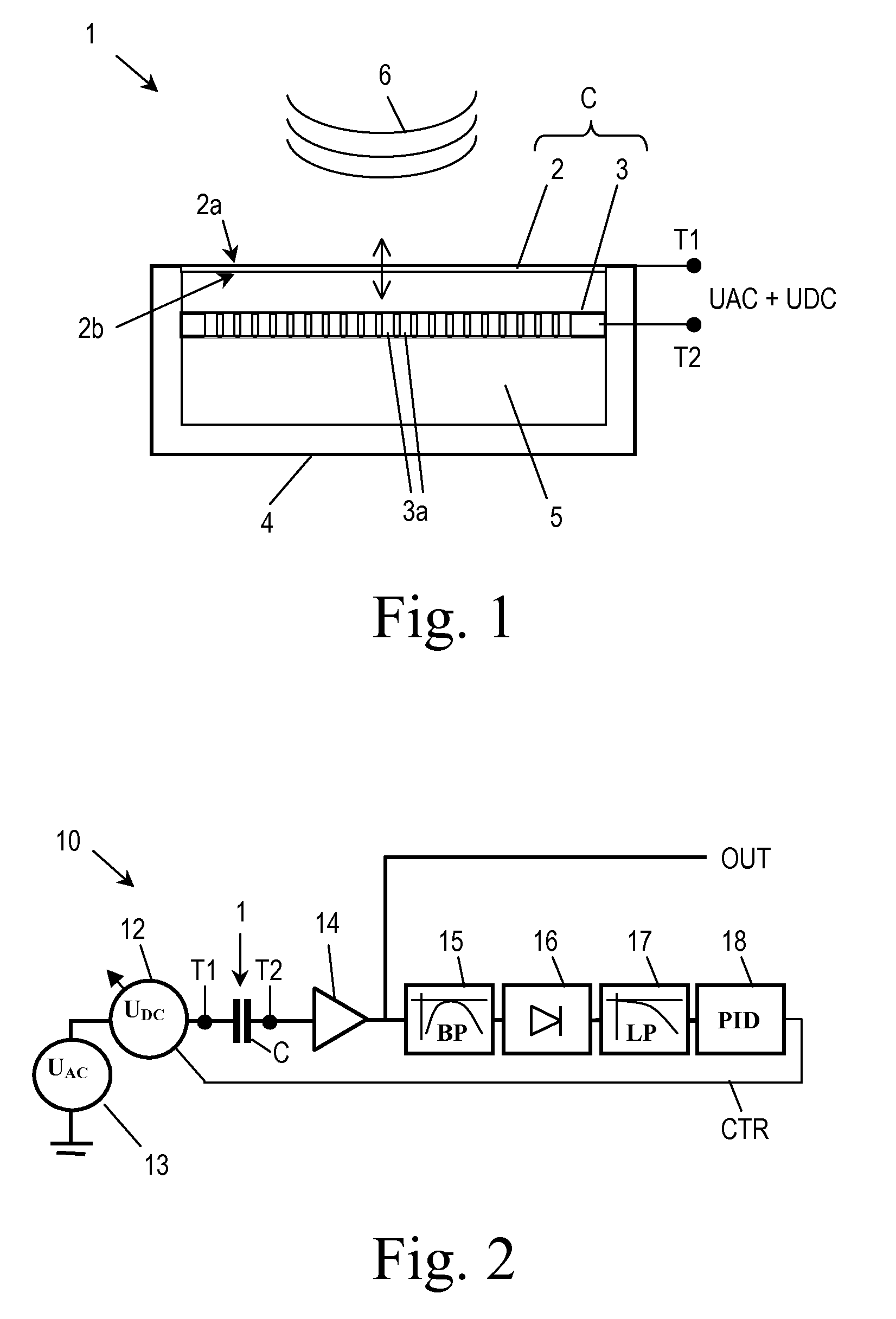
[0024]A capacitive pressure sensor 1, configured as a capacitive microphone, will be explained now with reference to the cross sectional representation of FIG. 1. The capacitive pressure sensor 1 generally comprises a very thin metallized diaphragm 2 that forms one plate electrode of a capacitor. An electrically conductive back plate 3 arranged in parallel to the diaphragm 2 forms a second plate electrode of the capacitor. The diaphragm 2 and the back plate 3 are connectable by means of terminals T1, T2 to an electronic circuit 10 (see FIG. 2) for controlling the capacitive pressure sensor 1, which circuit will be explained in detail later. Through the terminals T1, T2 the circuit 10 applies a DC bias-voltage UDC and an AC voltage signal UAC across the diaphragm 2 and the back plate 3. The diaphragm 2 is tightly stretched to have a resonant frequency that is considerably above the operating frequency range of the capacitive pressure sensor 1, e.g. at above 50 kHz, and is placed at a...


PUM


Abstract

An electronic circuit (10) for controlling a capacitive pressure sensor (1), which capacitive pressure sensor (1) comprises a plate electrode capacitor (C) with a capacity that varies in dependence on pressure changes exerted on a deflectable diaphragm (2) forming one plate electrode of the capacitor (C), wherein the electronic circuit (10) comprises a DC voltage source (12) being adapted to generate a DC bias-voltage (UDC) to be applied across the electrodes of the capacitor (C), an AC voltage source (13) being adapted to generate an AC voltage signal (UAC) to be applied across the electrodes of the capacitor (C) and a controller (18) being adapted to receive an output signal (OUT) of the capacitor (C) and to control the DC voltage source (12) such that the DC bias-voltage (UDC) applied to the capacitor (C) adopts a value that maintains the capacity of the capacitor (C) at a desired value.

Description

FIELD OF THE INVENTION[0001]The invention relates to an electronic circuit for controlling a capacitive pressure sensor. The invention further relates to a capacitive pressure sensor system.BACKGROUND OF THE INVENTION[0002]A capacitive pressure sensor, particularly a capacitive microphone, configured as a pressure difference sensor, generally comprises a very thin metallized diaphragm that forms one plate electrode of a capacitor and a back plate forming a second plate electrode of the capacitor. The diaphragm is tightly stretched to have a high resonant frequency, and is placed at a distance very close to the back plate. The diaphragm is deflected by a pressure difference between its front surface and its back surface, wherein the back surface of the diaphragm together with a housing of the pressure sensor encircles a back volume and seal it against the environment. Deflecting the diaphragm causes slight changes of the capacitance of the capacitor. The back volume constitutes a ref...

Claims


Application Information

Patent Timeline
IPC IPC(8): G01L9/12
CPCG01L9/12
Inventor LUTZ, JOSEF
Owner NXP BV
Why Eureka
Try Eureka