Electro-hydraulic actuator for controlling the pitch of a blade of a wind turbine

a technology of electric actuator and wind turbine, which is applied in the direction of rotors, marine propulsion, vessel construction, etc., can solve the problem of short life expectancy of such an arrangemen

Inactive Publication Date: 2010-09-16
GEIGER DAVID
View PDF19 Cites 20 Cited by
  • Summary
  • Abstract
  • Description
  • Claims
  • Application Information

AI Technical Summary

Benefits of technology

[0006]With parenthetical reference to the corresponding parts, portions or surfaces of the disclosed embodiment, merely for purposes of illustration and not by way of limitation, t...

Problems solved by technology

The life expectancy of such an arrangement has been as short as about four years due t...

Method used


Image

  • Electro-hydraulic actuator for controlling the pitch of a blade of a wind turbine
  • Electro-hydraulic actuator for controlling the pitch of a blade of a wind turbine
  • Electro-hydraulic actuator for controlling the pitch of a blade of a wind turbine

Examples


Embodiment Construction

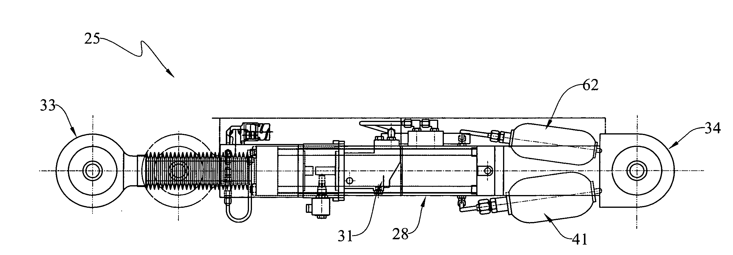
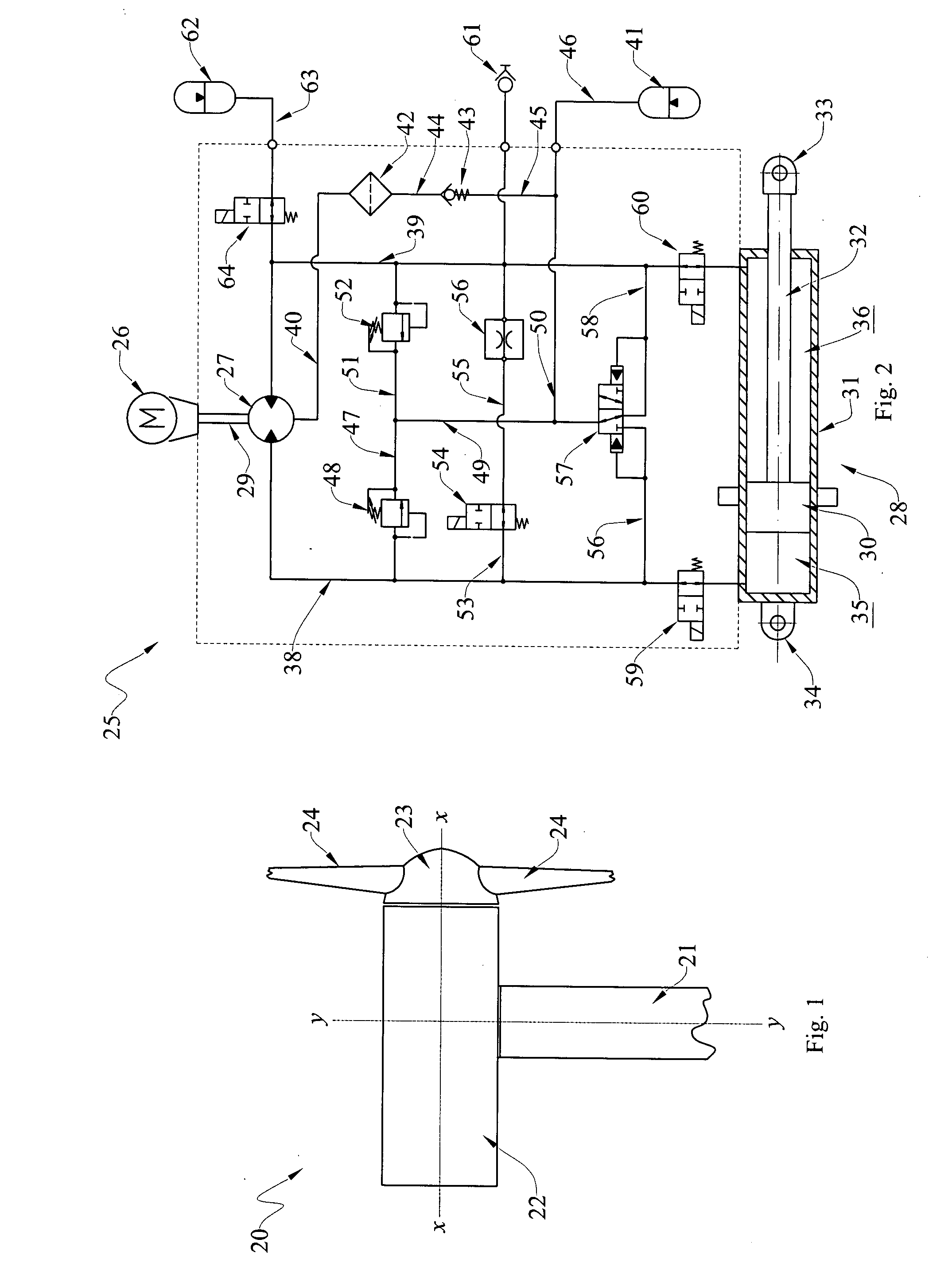
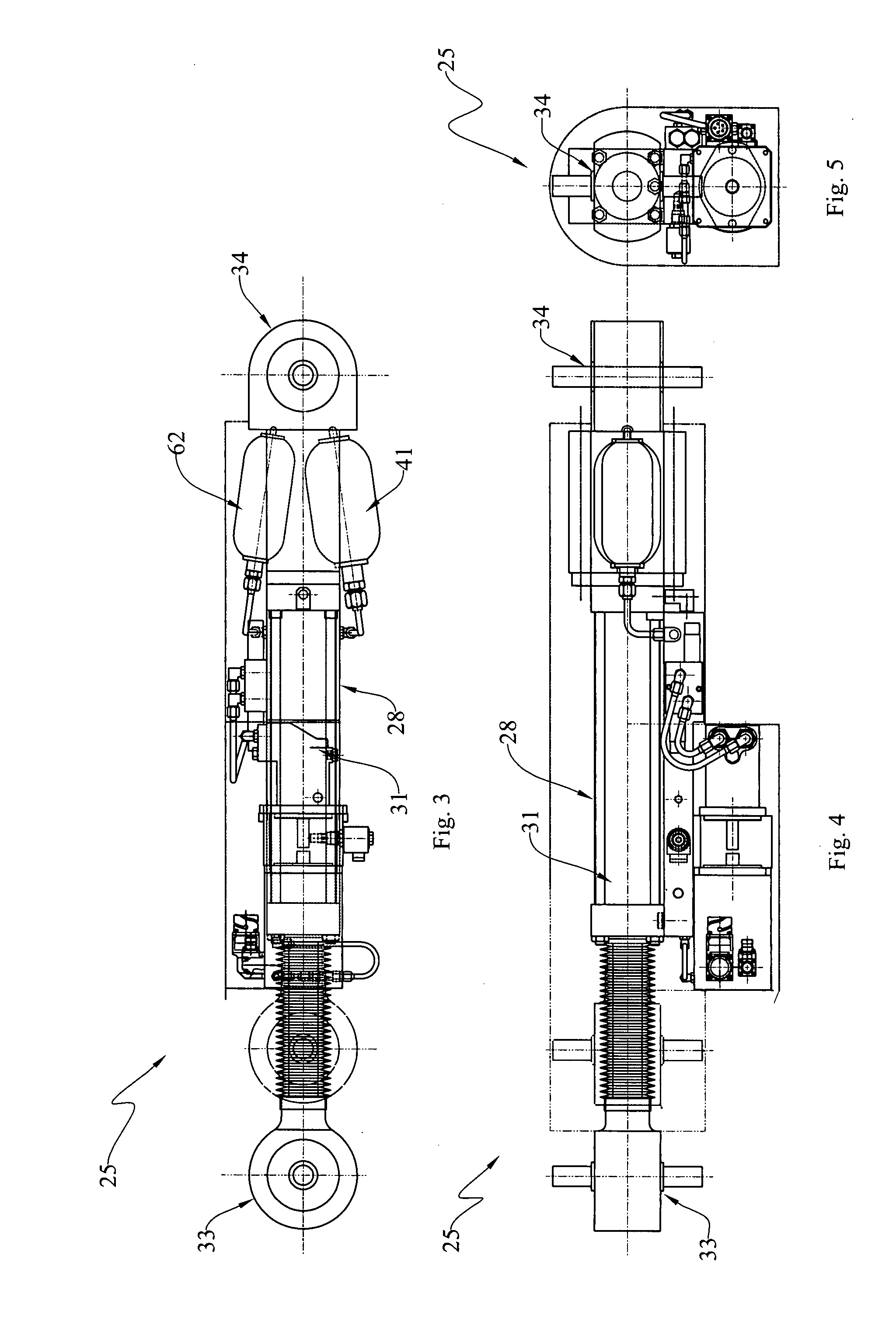
[0033]At the outset, it should be clearly understood that like reference numerals are intended to identify the same structural elements, portions or surfaces consistently throughout the several drawing figures, as such elements, portions or surfaces may be further described or explained by the entire written specification, of which this detailed description is an integral part. Unless otherwise indicated, the drawings are intended to be read (e.g., cross-hatching, arrangement of parts, proportion, degree, etc.) together with the specification, and are to be considered a portion of the entire written description of this invention. As used in the following description, the terms “horizontal”, “vertical”, “left”, “right”, “up” and “down”, as well as adjectival and adverbial derivatives thereof (e.g., “horizontally”, “rightwardly”, “upwardly”, etc.), simply refer to the orientation of the illustrated structure as the particular drawing figure faces the reader. Similarly, the terms “inwa...


PUM


Abstract

The present invention provides an improvement for use in a wind turbine (20) having a plurality of variable-pitch blades (24) mounted on a hub (23) for rotation relative to a nacelle (22). The improvement broadly includes: a electro-hydraulic actuator (25) for controlling the pitch of one of the blades, the actuator including: a motor (26) adapted to be supplied with a current; a pump (27) driven by the motor and arranged to provide a hydraulic output as a function of the current supplied to the motor; and a hydraulic actuator (28) operatively arranged to selectively vary the pitch of the associated blade as a function of the hydraulic output of the pump; and wherein the motor, pump and actuator are physically arranged within the hub of the wind turbine.

Description

TECHNICAL FIELD[0001]The present invention relates generally to the field of wind turbines, and, more particularly, to an improved wind turbine having a plurality of electro-hydraulic actuators mounted on the rotatable hub of the turbine for independently controlling the pitch of a like plurality of blades.BACKGROUND ART[0002]Wind turbines are, of course, known. In recent years, many of the problems of having a wind turbine supply power synchronously to an electrical grid have been addressed and overcome.[0003]Wind turbines today are relatively sophisticated. They are typically mounted on a tower, and have plurality of blades (normally three) mounted on a hub for rotation about a horizontal axis relative to a nacelle. The nacelle may be aimed into the direction of the oncoming wind. Each of the blades is typically of variable pitch, and the pitch of each blade may be controlled independently of the others. These blades are typically arranged at 120° intervals. When one blade is poin...

Claims


Application Information

Patent Timeline
IPC IPC(8): F01D7/00
CPCF03D7/0224Y02E10/723F05B2270/604F05B2260/76Y02E10/72
Inventor GEIGER, DAVID
Owner GEIGER DAVID
Why Eureka
Try Eureka