
Method for electromagnetic air-wave suppression by active cancellation and shielding

a shielding and electromagnetic technology, applied in seismology for waterlogging, instruments, reradiation, etc., can solve the problems of air wave effect, air wave interference, air wave noise, etc., to reduce electromagnetic energy traveling, reduce air wave noise, and reduce air wave nois

Active Publication Date: 2010-09-16
EXXONMOBIL UPSTREAM RES CO
View PDF13 Cites 11 Cited by
  • Summary
  • Abstract
  • Description
  • Claims
  • Application Information

AI Technical Summary

Benefits of technology

[0020](ii) deploying a conducting shield above the electromagnetic source so as to prevent source signal from escaping the subterranean region into the air above, thereby reducing air wave noise; and
[0021](iii) deploying a conducting shield above a receiver to reduce electromagnetic energy traveling downward toward the receiver, thereby reducing air wave and MT noise; and

Problems solved by technology

Air wave interference is a problem when measurements are made in the frequency domain, i.e., when the source continues to transmit its signals while data are being collected at the receivers.
Matters would be even worse for field data with MT noise.
The results from this example clearly demonstrate the problem of the air wave effect.
In the shallow-water case, however, the air wave and MT noise can have significant amplitude that masks the desired signals.
While all of these methods work to some extent, the existence of a very large air-wave component means that inaccuracies in the methods can lead to substantial residual noise.
Although Ez can be a helpful addition, its drawbacks include the smaller signal strength (causing greater MT noise problems), the remaining air-wave effect that still occurs in Ez, and the additional air-wave noise that is recorded on an Ez receiver when it is not perfectly vertical.
By reciprocity, there are similar issues (e.g., small signal, sensitivity to alignment).
Also, there may be logistics issues in operating a moving vertical electric source in the ocean.
The result is a very small signal that could have substantial ambient-noise problems.
MT noise in the field data, however, can compromise the results leaving residual air-wave effects.
This decomposition is an approximation and coupled with data noise can lead to incomplete airwave suppression.

Method used


Image

  • Method for electromagnetic air-wave suppression by active cancellation and shielding
  • Method for electromagnetic air-wave suppression by active cancellation and shielding
  • Method for electromagnetic air-wave suppression by active cancellation and shielding

Examples


examples

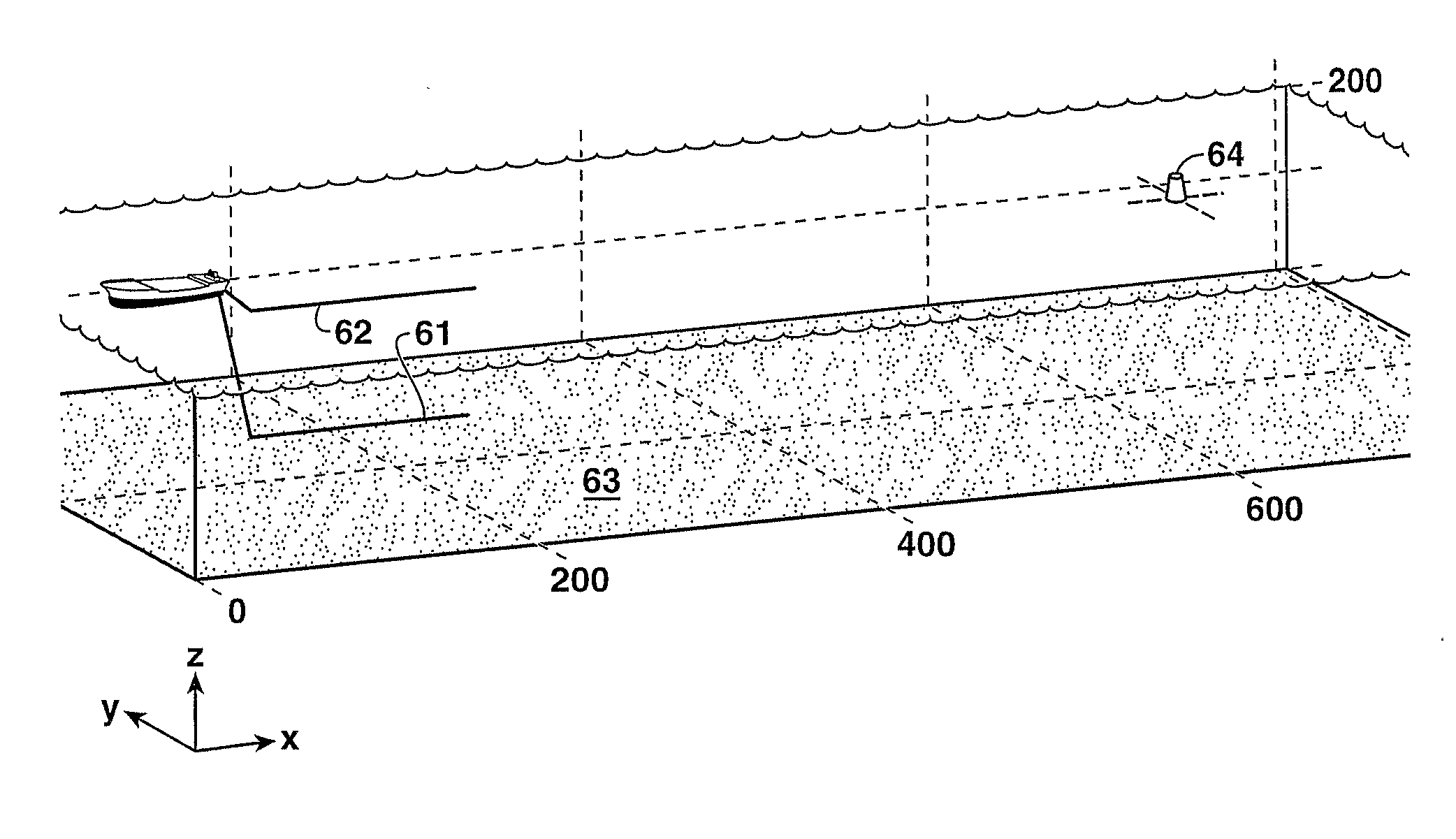
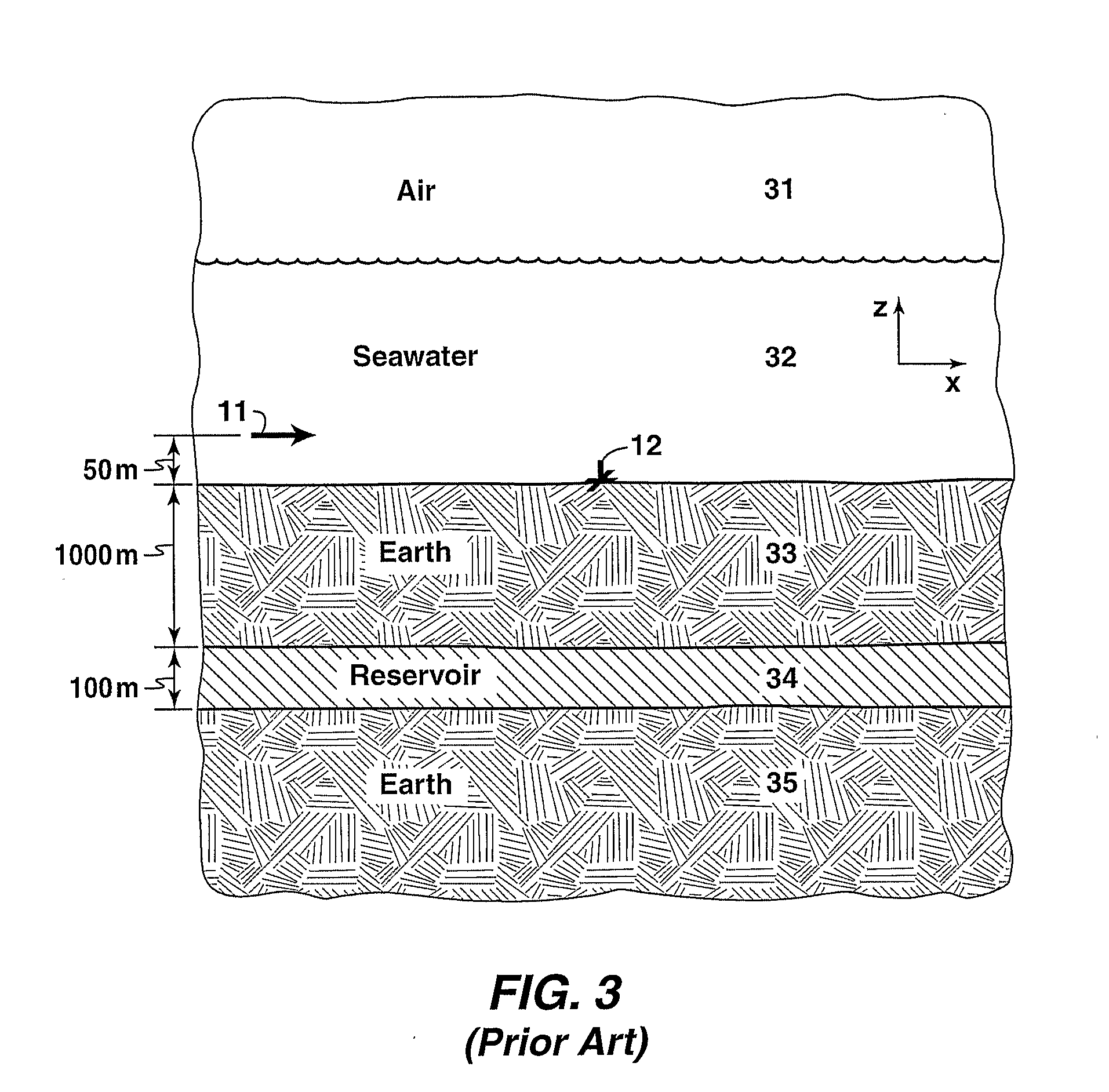
[0059]In the following two examples, 3D finite-element modeling is used to predict expected levels of air-wave suppression for a specified simple 1D earth model. The model uses a 1.25 Hz single frequency bipole source of 300 m length and moment of 1 A-m (for the primary source). The water is 120 m deep (5 S / m conductivity). The primary source bipole is 20 m above the water bottom while the secondary (when used) is 20 m from the top of the water giving a separation of 80 m. Below the water layer is 700 m of shale (0.714 S / m vertical and 1.333 S / m horizontal conductivity). Below this is a 100 m reservoir (0.02 S / m conductivity) and a half space of shale (same as above). This 1-D model can be seen reflected in FIGS. 10A-B and 12A-B. The signal-to-noise ratio (SNR) in these examples is defined as the average total electric field in the reservoir at distances greater than 5 km divided by the average total electric field in the air also at distances greater than 5 km from the source(s).

[0...


PUM


Abstract

Method for reducing air wave and / or magnetotelluric noise in controlled source electromagnetic surveying by either shielding the source (61) from the air interface, shielding the receivers from downward traveling electromagnetic energy, or by employing a second source (62) to preferentially cancel the air wave (and MT) part of the signal, or a combination of the preceding.

Description

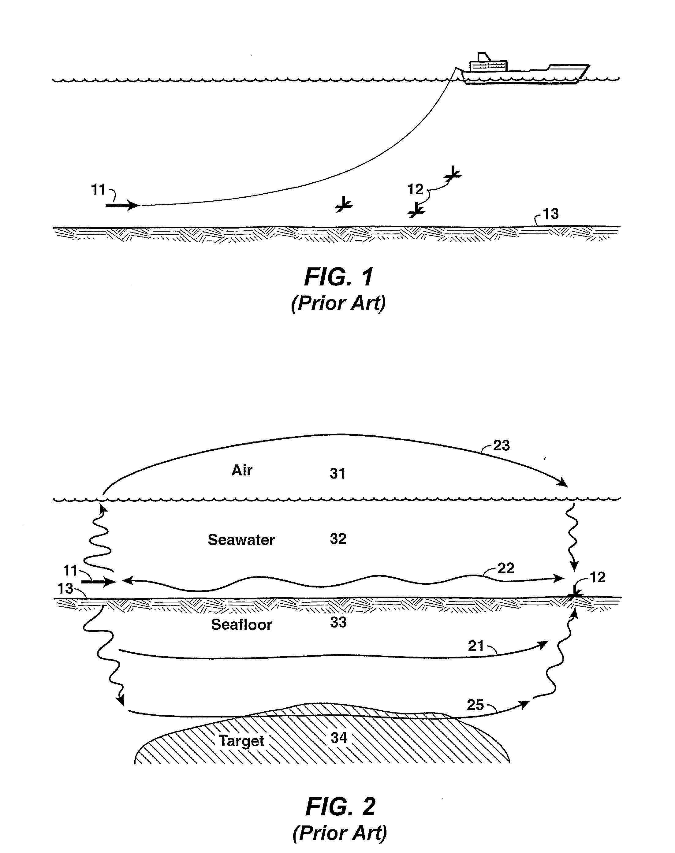
[0001]This application claims the benefit of U.S. Provisional Application No. 60 / 775,061 filed, on Feb. 21, 2006.FIELD OF THE INVENTION[0002]This invention relates generally to the field of geophysical prospecting and, more particularly to controlled source electromagnetic (“CSEM”) surveying for hydrocarbons. Specifically, this invention is a method for addressing the air-wave problem that occurs in CSEM exploration in shallow water or on land.BACKGROUND OF THE INVENTION[0003]The controlled source electromagnetic survey method in a marine environment uses an applied source for mapping sub-seafloor resistivity variations; see, for example, U.S. Pat. No. 6,603,313 to Srnka. FIG. 1 is a schematic diagram of such a survey, with electromagnetic source 11 connected by cable to a vessel and receivers 12 located in the ocean, and often on the seafloor 13. The measured fields are analyzed to investigate the sub-sea floor structures of the earth's interior.[0004]The electromagnetic signals re...

Claims


Application Information

Patent Timeline
IPC IPC(8): H04B13/02
CPCG01V3/083G01V3/15G01V3/17G01V3/38
Inventor HORNBOSTEL, SCOTT C.ROSS, WARREN S.SRNKA, LEONARD J.
Owner EXXONMOBIL UPSTREAM RES CO
Learn More