Control of throttle and braking actions at individual distributed power locomotives in a railroad train

a technology of distributed power trains and throttles, which is applied in the direction of brake systems, process and machine control, instruments, etc., can solve the problems of long distributed power trains that are difficult to control, destructively hazardous situations, and the wheels of railcars to overhea

Active Publication Date: 2010-09-16
GE GLOBAL SOURCING LLC
View PDF24 Cites 83 Cited by
  • Summary
  • Abstract
  • Description
  • Claims
  • Application Information

AI Technical Summary

Benefits of technology

[0016]One embodiment of the invention comprises a method for controlling first and second locomotives of a railroad train, the first and the second locomotives separated by at least one railcar. The method comprises determining a location of the first locomotive and a location of the second locomotive, determining an operating condition of the first locomotive and an operating condition of the second locomotive,

Problems solved by technology

Use of the dynamic brakes is indicated to slow the train when application of the locomotive independent brakes and/or the railcar air brakes may cause the locomotive or railcar wheels to overheat or when their prolonged use may cause excessive wheel wear.
Long distributed power trains are often difficult to control when cresting hills (transitioning from steep uphill to steep downhill grades).
If the train accelerates significantly when stretched over the crest, the operator can lose control of the train, creating a destructively hazardous situation.
When the train is in synchronous mode, if the operator applies the railcar and/or the independent locomotive brakes while one or more remote locomotives and a significant number of ra

Method used


Image

  • Control of throttle and braking actions at individual distributed power locomotives in a railroad train
  • Control of throttle and braking actions at individual distributed power locomotives in a railroad train
  • Control of throttle and braking actions at individual distributed power locomotives in a railroad train

Examples


Embodiment Construction

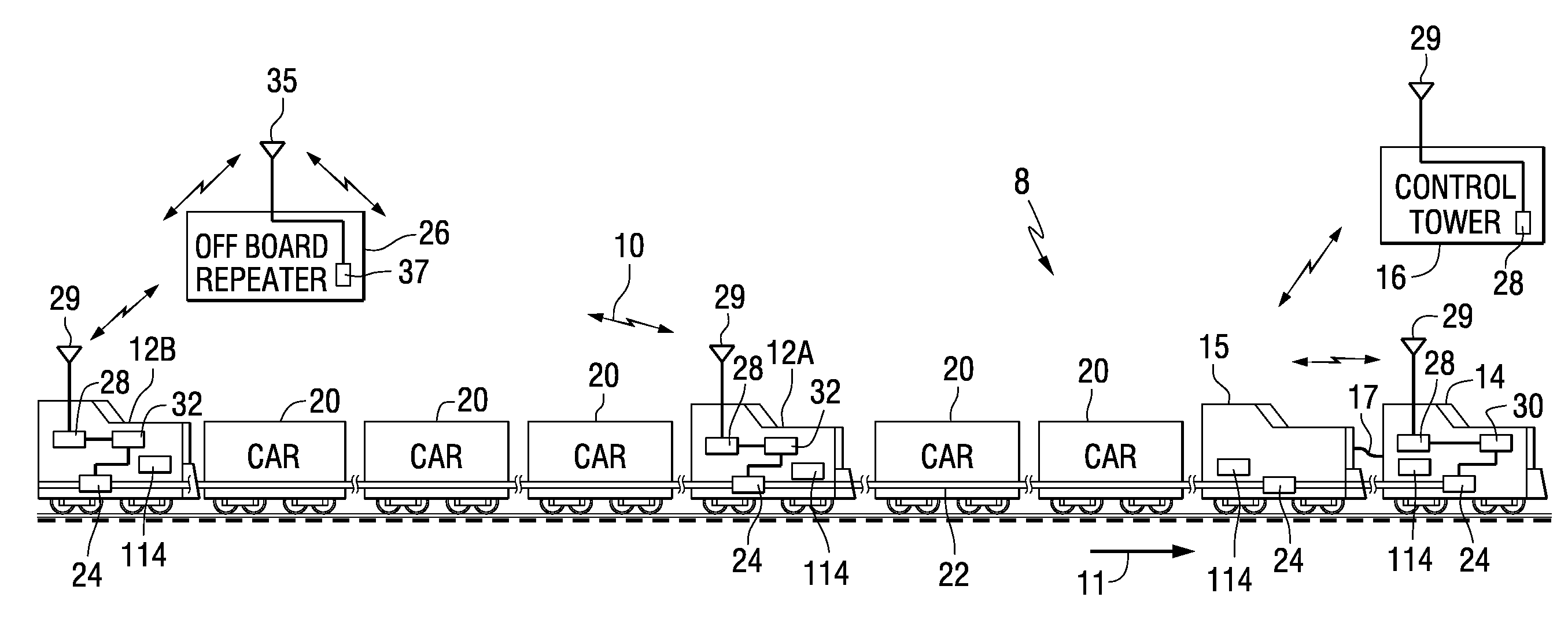
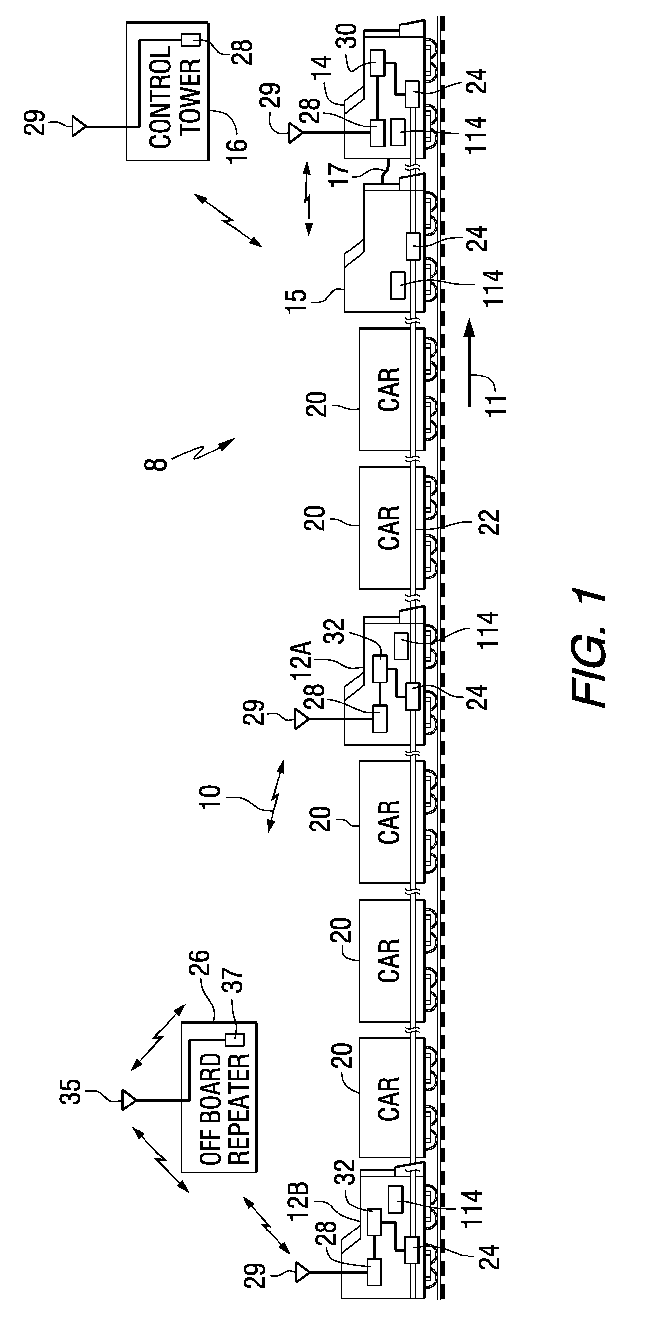
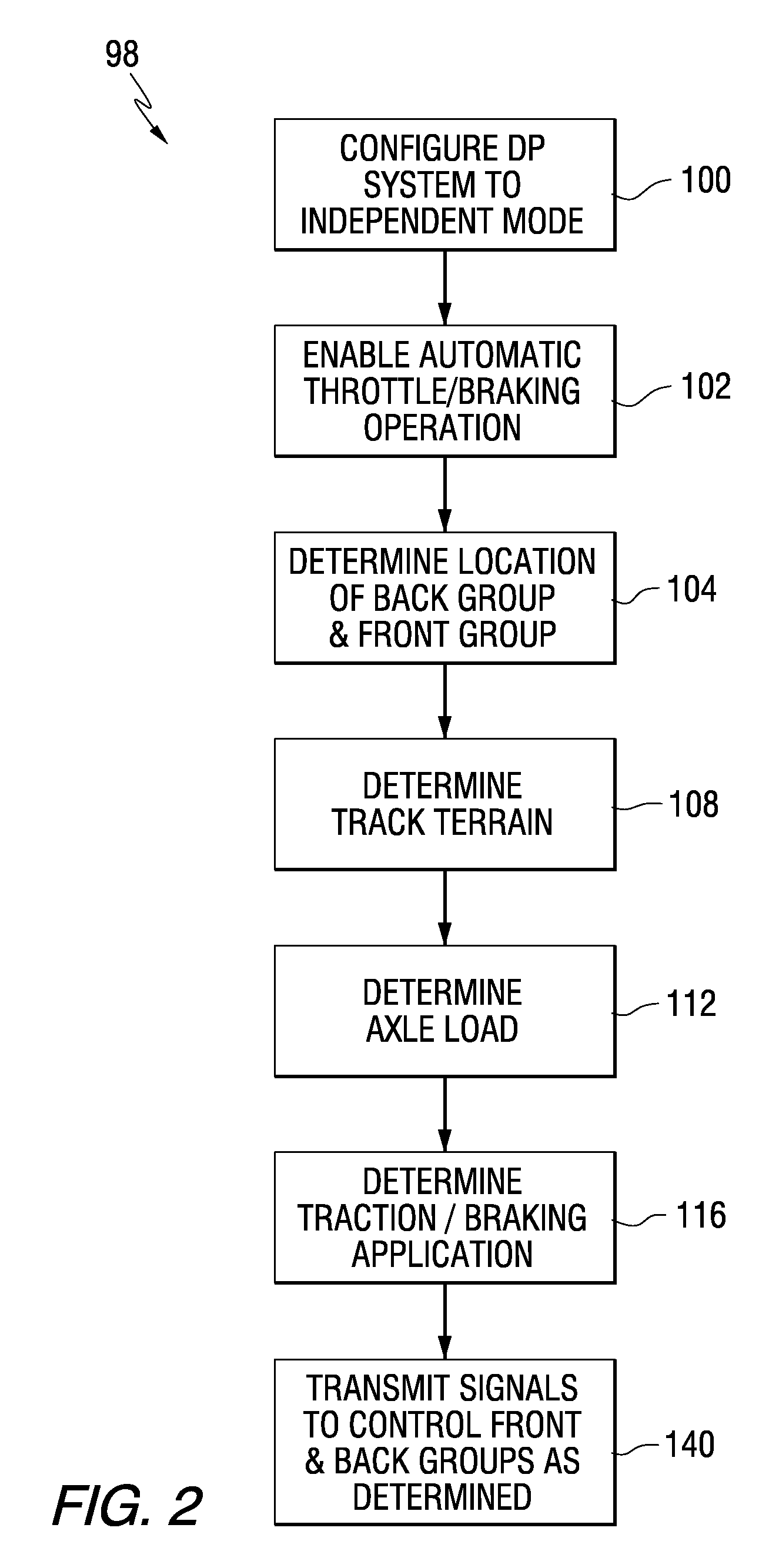
[0029]Before describing in detail the methods and apparatuses in accordance with the embodiments of the present invention, it should be observed that the inventive nature of the various embodiments resides primarily in a novel combination of hardware and software elements related to the methods and apparatuses. Accordingly, the hardware and software elements have been represented by conventional elements in the drawings, showing only those specific details that are pertinent to the embodiments of the invention, so as not to obscure the disclosure with structural details that will be readily apparent to those skilled in the art having the benefit of the description herein. All singular nouns are intended to include the plural form of the noun and vice versa.

[0030]The following embodiments are not intended to define limits as to the structures or methods of the invention, but only to provide exemplary constructions. The embodiments are permissive rather than mandatory and illustrative...


PUM


Abstract

A method for controlling first (14/12A) and second (12B) locomotives of a railroad train (8), the first (14/12A) and the second (12B) locomotives separated by at least one railcar (20). The method comprises determining a location of the first locomotive (14/12A) and a location of the second locomotive (12B), determining an operating condition of the first locomotive (14/12A) and an operating condition of the second locomotive (12B), determining a first control aspect of the first locomotive (14/12A) responsive to the operating condition and the location of the first locomotive (14/12A), determining a second control aspect of the second locomotive (12B) responsive to the operating condition and the location of the second locomotive (12B), and controlling the first (14/12A) and the second (12B) locomotives according to the first control aspect and the second control aspect, respectively.

Description

FIELD OF THE INVENTION[0001]The subject matter disclosed herein relates to a railroad train control system for use with a distributed power train comprising a lead locomotive and one or more remote locomotives.BACKGROUND OF THE INVENTION[0002]Under operator control, a railroad locomotive supplies motive power (traction) to move a train and applies brakes on the locomotive and / or on train railcars to slow or stop the train. The motive power is supplied by electric traction motors responsive to an AC or DC voltage generated by the locomotive engine.[0003]The railroad train comprises three separate brake systems. An air brake system comprises a fluid-carrying brake pipe that extends a length of the train and connects to each rail car. An operator in the lead locomotive controls the fluid pressure in the brake pipe and each rail car responds to the sensed pressure. At each rail car, car brakes are applied responsive to a decrease in the sensed fluid pressure and released responsive to a...

Claims


Application Information

Patent Timeline
IPC IPC(8): G06F17/00
CPCB61C17/12B61L2205/04B61L25/025B61L3/006
Inventor SIDDAPPA, CHANDRASHEKARMOFFITT, ROBERT
Owner GE GLOBAL SOURCING LLC
Why Eureka
Try Eureka