Avoidance maneuver calculation device, avoidance control device, vehicle having each device, avoidance maneuver calculating method, and avoidance controlling method

a technology of avoidance maneuver and calculation device, which is applied in the direction of anti-collision system, external condition input parameters, vehicle registration/indicating, etc., and can solve the problems of driver discomfort and burdensome steering

Active Publication Date: 2010-09-16
NISSAN MOTOR CO LTD
View PDF4 Cites 78 Cited by
  • Summary
  • Abstract
  • Description
  • Claims
  • Application Information

AI Technical Summary

Benefits of technology

[0007]When calculating the maneuver amount for avoiding the obstacle, the avoidance maneuver calculation device according to the present invention calculates the maneuver amount in consideration of the boundary section of the road in addition to the obstacle. Specifically, the avoidance maneuver calculation device calculates the maneuver amount that enables the automotive vehicle to avoid the obstacle within a width of the road, i.e. within a travelable range. For this reason, even when fences are provided on both sides of the road, for example, it is possible to calculate the maneuver amount that enables the automotive vehicle to avoid the obstacle and to return to a track taken before the avoidance without coming too close to an end.

Problems solved by technology

This steering is burdensome to the driver.
Moreover, the driver experiences a discomfort as the traveling direction of the automotive vehicle deviates from the direction of the road.

Method used


Image

  • Avoidance maneuver calculation device, avoidance control device, vehicle having each device, avoidance maneuver calculating method, and avoidance controlling method
  • Avoidance maneuver calculation device, avoidance control device, vehicle having each device, avoidance maneuver calculating method, and avoidance controlling method
  • Avoidance maneuver calculation device, avoidance control device, vehicle having each device, avoidance maneuver calculating method, and avoidance controlling method

Examples


first embodiment

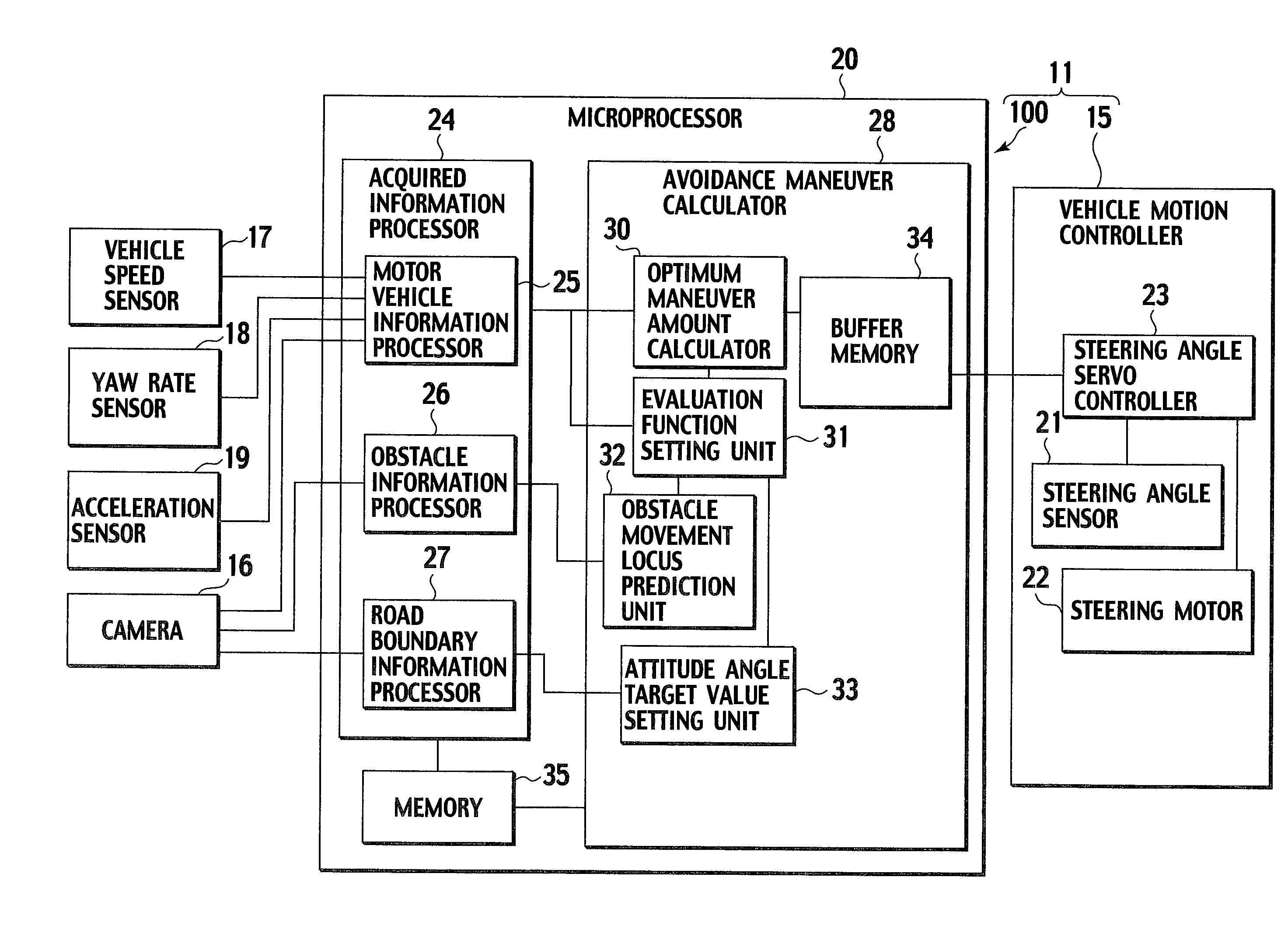
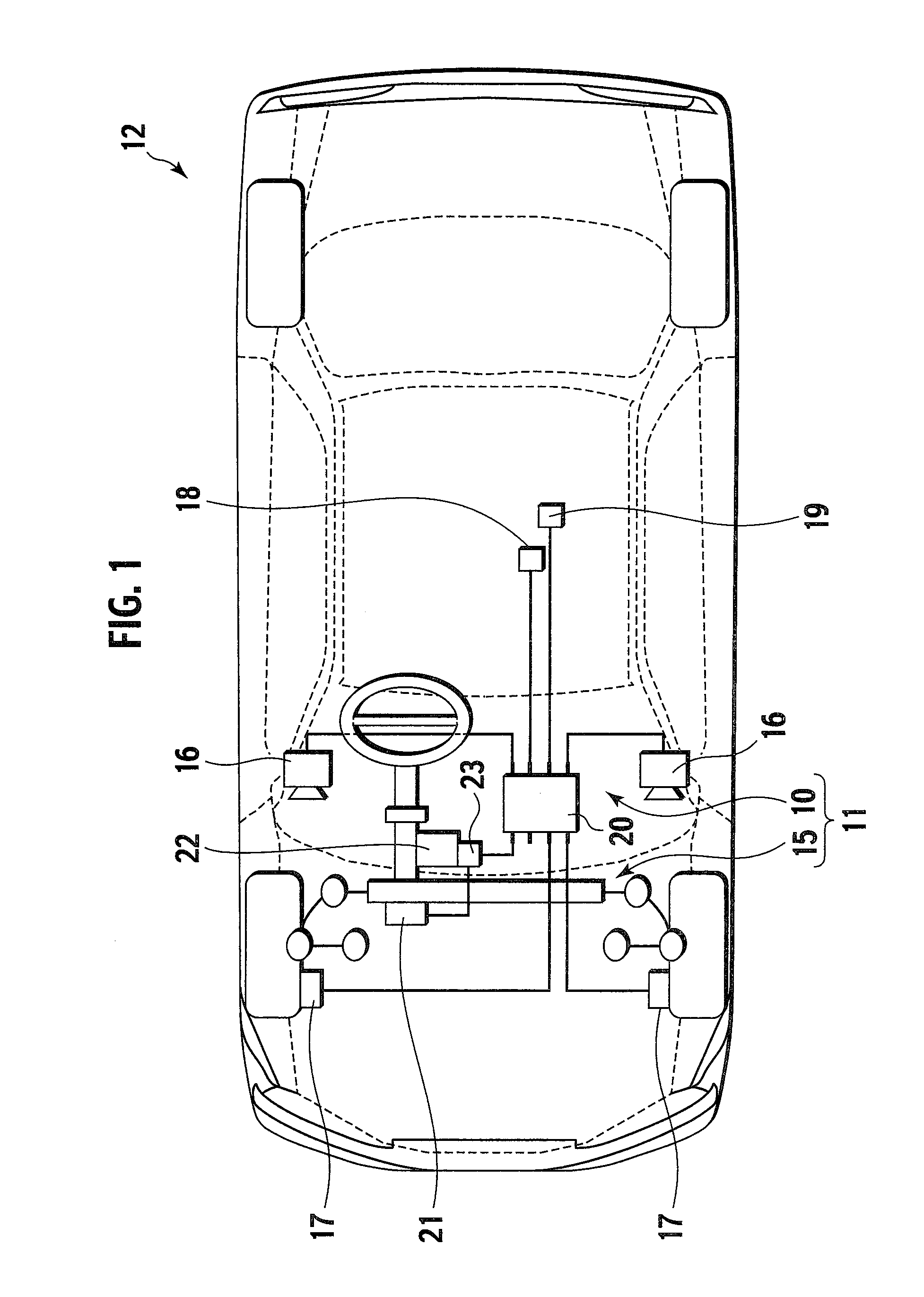
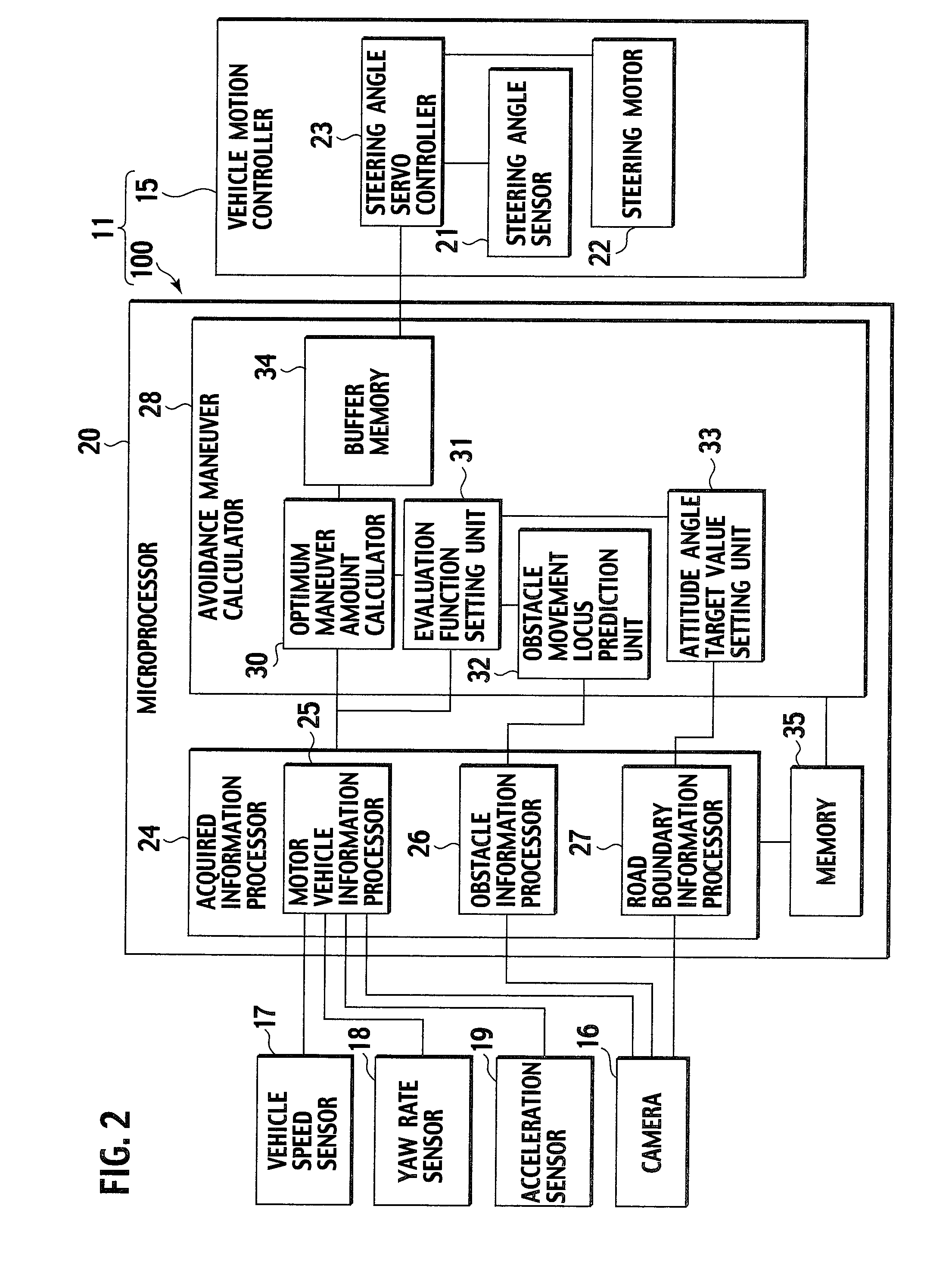
[0030]FIG. 1 is a plan view schematically showing a vehicle 12 employing an avoidance maneuver calculation device 10 and an avoidance control device 11 which includes the avoidance maneuver calculation device 10, according to the embodiment. FIG. 2 is a block diagram showing the avoidance control device 11.

[0031]When an obstacle 14 (see FIG. 3) exists on a road 13 where a vehicle 12 (an automotive vehicle) is traveling, the avoidance maneuver calculation device 10 calculates a driving maneuver amount that enables the vehicle 12 to avoid the obstacle 14. The avoidance control device 11 includes the avoidance maneuver calculation device 10 and a vehicle motion controller 15. The vehicle motion controller 15 performs driving maneuver by the driving maneuver amount calculated by the avoidance maneuver calculation device 10.

[0032]The vehicle 12 is provided with cameras 16, vehicle speed sensors 17, a yaw rate sensor 18, an acceleration sensor 19, a microprocessor 20, a steering angle sen...

second embodiment

[0101]Based on the drawings in FIG. 12 to FIG. 16, description will be given of an avoidance maneuver calculation device 100 and an avoidance control device 110 including the avoidance maneuver calculation device 100, according to a second embodiment of the present invention.

[0102]In the second embodiment of the present invention, as shown in FIG. 13, a road 40 where the vehicle 12 is traveling is partitioned into two lanes 42 and 43 by drawing a lane dividing line 41, so that the lane 42 and the lane 43 allow the vehicle 12 to travel in opposite directions. Meanwhile, the avoidance maneuver calculation device 100 (see FIG. 12) of the second embodiment calculates the optimum driving maneuver amount which can deal with variation in the traveling speed of the obstacle 14 on the road 40. In the second embodiment, the lane dividing line 41 is a broken line to partition the road 40 into the lanes having the different traveling directions. Note that, however, it may be a line to partition...

third embodiment

[0119]Based on the drawings in FIGS. 17 to 21, description will be given of an avoidance maneuver calculation device 1000 and an avoidance control device 1100 including the avoidance maneuver calculation device 1000, according to a third embodiment of the present invention.

[0120]The avoidance maneuver calculation device 1000 and the avoidance control device 1100 including the avoidance maneuver calculation device 1000 (see FIG. 18) of the third embodiment basically have the same configurations and operations as the avoidance maneuver calculation device 10 and the avoidance control device 11 including the avoidance maneuver calculation device 10 of the first embodiment. The same constituents are designated by the same reference numerals and detailed description thereof will be omitted. Likewise, detailed description of the same operations will be omitted.

[0121]In the third embodiment, the avoidance maneuver calculation device 1000 includes a GPS signal receiving device 50 and a road ...


PUM


Abstract

Provided is an avoidance maneuver calculation device that calculates a driving maneuver amount that enables an automotive vehicle to avoid an obstacle within a travelable range of a road. The device includes: a road boundary detector for detecting a road 13 where a vehicle 12 is traveling and a boundary section thereof; an obstacle detector for detecting an obstacle 14 existing on the road 13; an automotive vehicle information detector for detecting information on the vehicle 12; and an avoidance maneuver calculator 28 for calculating a maneuver amount for avoiding the obstacle 14 on the road 13.

Description

TECHNICAL FIELD[0001]The present invention relates to an avoidance maneuver calculation device, an avoidance control device, a vehicle having each device, an avoidance maneuver calculating method, and an avoidance controlling method for avoiding an obstacle on a road where an automotive vehicle is traveling.BACKGROUND ART[0002]A conventional traveling safety device is configured to detect an obstacle on a road where an automotive vehicle is traveling and to maneuver the automotive vehicle by driving an actuator for electric power steering upon detection of the obstacle. Thereby, the automotive vehicle avoids the obstacle. When trying to avoid an obstacle, this traveling safety device deflects a traveling direction of the automotive vehicle from a direction of the road, i.e. the direction along a track shape of the road. Accordingly, a driver needs to perform steering to bring the traveling direction of the automotive vehicle back to the direction of the road. This steering is burden...

Claims


Application Information

Patent Timeline
Patent Type & Authority Applications(United States)
IPC IPC(8): G08G1/16G06F7/00B60R11/02B60R21/00B60T7/12B60T8/1755B60W10/18B60W10/184B60W10/20B60W30/00B60W30/09B62D6/00B62D101/00B62D111/00B62D137/00
CPCB60T7/22B60T2201/022B60T2201/082B60W10/18B60W10/20B60W30/09G08G1/167B60W2050/0033B60W2550/20B60W2550/402B62D15/0265G08G1/16B60W30/095B60W2554/00B60W2556/50G08G1/165G08G1/166
Inventor NISHIRA, HIKARUDEGUCHI, YOSHITAKA
Owner NISSAN MOTOR CO LTD
Why Eureka
Try Eureka