Turbofan engine with variable area fan nozzle and low spool generator for emergency power generation and method for providing emergency power

a technology of variable area fan nozzle and low spool generator, which is applied in the direction of machines/engines, marine propulsion, vessel construction, etc., can solve the problems of increase and achieve the effect of increasing the rotational speed of the fan and reducing the effective nozzle exit area

Active Publication Date: 2010-09-23
RTX CORP
View PDF5 Cites 38 Cited by
  • Summary
  • Abstract
  • Description
  • Claims
  • Application Information

AI Technical Summary

Problems solved by technology

Upon sensing an emergency condition in which the fan drives the generator, the controller manipulates the flow control device to reduce the effective nozzle exit area, which chokes the flow through the fan duct thereby increasing the rotational speed of the fan.

Method used


Image

  • Turbofan engine with variable area fan nozzle and low spool generator for emergency power generation and method for providing emergency power
  • Turbofan engine with variable area fan nozzle and low spool generator for emergency power generation and method for providing emergency power
  • Turbofan engine with variable area fan nozzle and low spool generator for emergency power generation and method for providing emergency power

Examples


Embodiment Construction

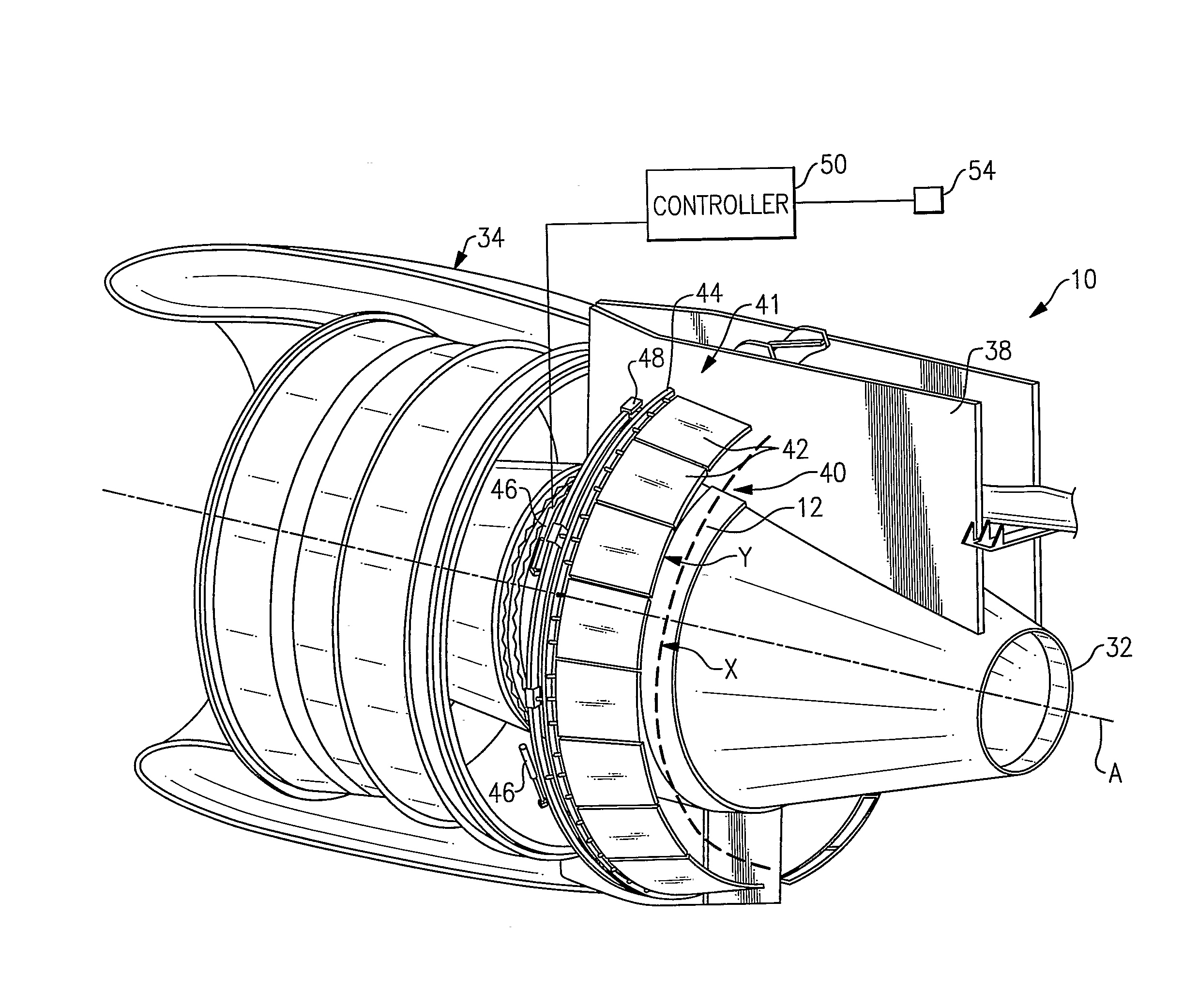
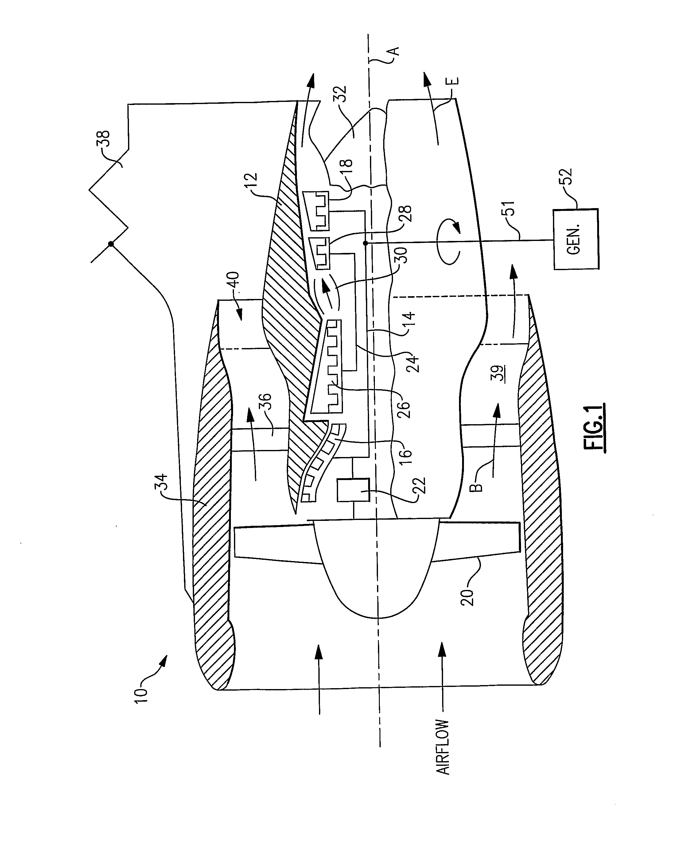
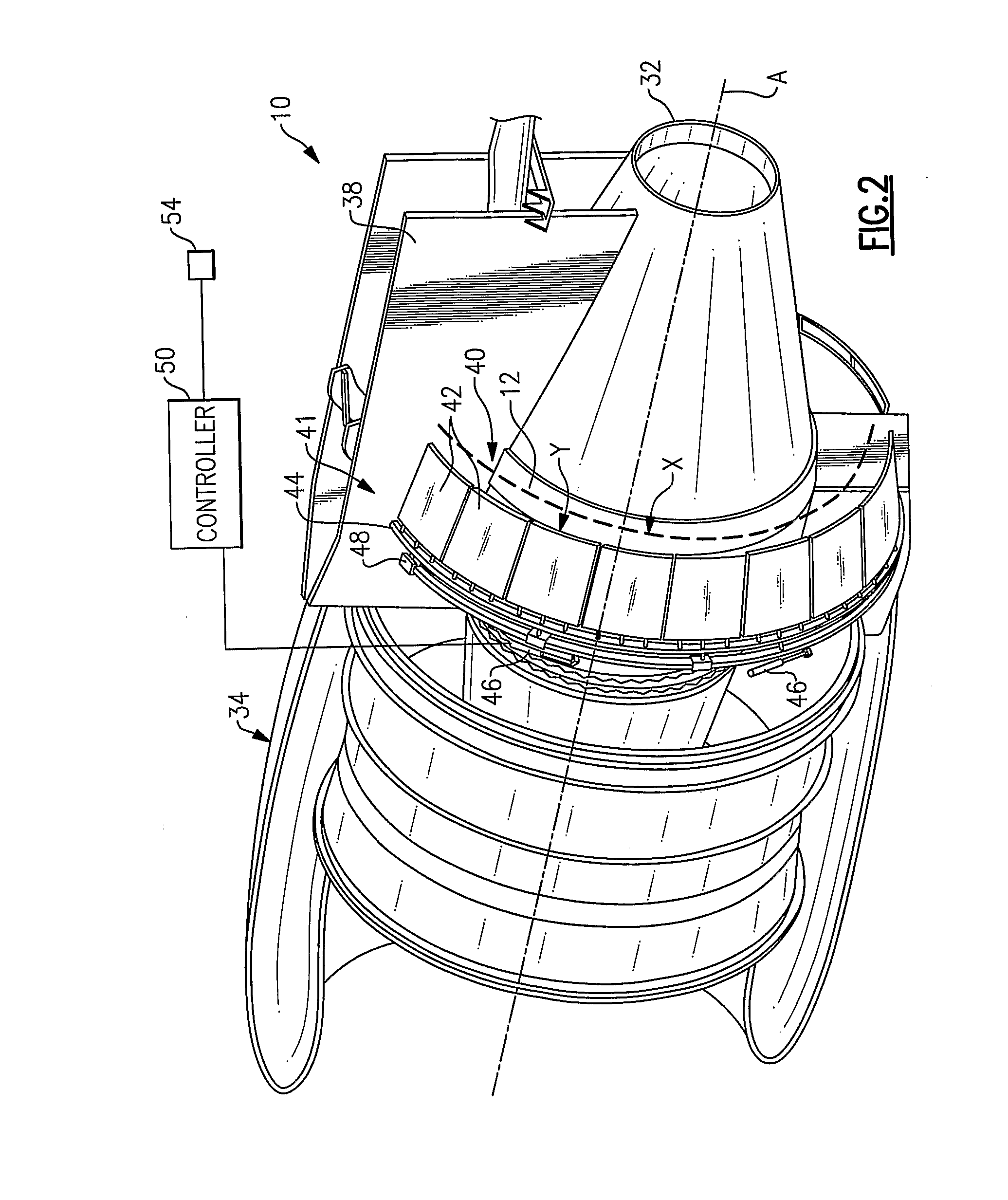
[0009]A geared turbofan engine 10 is shown in FIG. 1. A pylon 38 supports the engine 10 on an aircraft. The engine 10 includes a core nacelle 12 that houses a low spool 14 and high spool 24 rotatable about an axis A. The low spool 14 supports a low pressure compressor 16 and low pressure turbine 18. In the example, the low spool 14 drives a fan 20 through a gear train 22. The high spool 24 supports a high pressure compressor 26 and high pressure turbine 28. A combustor 30 is arranged between the high pressure compressor 26 and high pressure turbine 28. Compressed air from compressors 16, 26 mixes with fuel from the combustor 30 and is expanded in turbines 18, 28.

[0010]In the examples shown, the engine 10 is a high bypass turbofan arrangement. In one example, the bypass ratio is greater than 10:1, and the fan diameter is substantially larger than the diameter of the low pressure compressor 16. The low pressure turbine 18 has a pressure ratio that is greater than 5:1, in one example. ...


PUM


Abstract

A turbofan engine (10) employs a flow control device (41) that changes an effective exit nozzle area (40) associated with a bypass flow path (B) of the turbofan engine. A spool (14) couples a fan (20) to a generator (52). The turbofan emergency power system includes a controller (50) that communicates with the flow control device (41). Upon sensing an emergency condition, the controller manipulates the flow control device to reduce the effective nozzle exit area (40) of the bypass flow path, which chokes the flow through the bypass flow path thereby increasing the rotational speed of the fan. In this manner, the generator is driven at a higher rotational speed than if the flow through the bypass flow path was not choked, which enables a smaller generator to be utilized.

Description

BACKGROUND OF THE INVENTION[0001]This invention relates to a method and apparatus for employing emergency power in a turbofan engine.[0002]Many commercial aircraft employ ram air turbines (RAT) as sources of emergency power in conditions where all main propulsions engines have failed. The RAT deploys from the aircraft fuselage and turbine blades unfold so that they may be driven by the aircrafts' forward motion. The turbine drives a hydraulic pump and / or electric generator. The RAT adds weight and cost to the aircraft. RATs must be checked periodically to ensure their operability since they are not deployed during normal aircraft usage.[0003]Turbofan engines have been designed in which the fan is used to drive a generator in emergencies. In a turbofan engine, a flow path is arranged in the fan duct formed between core and fan nacelles. When the engine loses power, the fan rotationally drives a generator during a windmilling condition in which the fan is rotationally driven by airflo...

Claims


Application Information

Patent Timeline
Patent Type & Authority Applications(United States)
IPC IPC(8): F02C9/18F02C7/32F02K3/06
CPCF01D21/00F02C3/113F02C7/262F05D2270/061Y02T50/671F05D2270/092F02C7/32Y02T50/60
Inventor WINTER, MICHAELLENTS, CHARLES E.
Owner RTX CORP
Why Eureka
Try Eureka