Methods and apparatus for integrated energy harvesting power sources and inertial sensors for gun-fired munitions

a technology of inertial sensor and power source, applied in the field of power supplies, can solve the problems of significant power requirement, and achieve the effect of reducing the number of power supply components

Active Publication Date: 2010-09-23
OMNITEK PARTNERS LLC
View PDF2 Cites 14 Cited by
  • Summary
  • Abstract
  • Description
  • Claims
  • Application Information

AI Technical Summary

Benefits of technology

[0013]It is noted that the disclosed power generators with integrated inertial sensors may also be used in devices that only experience high acceleration levels upon impacting certain object or medium. In such applications, the present power generators with integrated inertial sensors can be used to determine the direction of the imp

Problems solved by technology

The power requirement, however, becomes significant when the projectile has to be equipped with electric or smart materials based actuation devices for guidance and control

Method used


Image

  • Methods and apparatus for integrated energy harvesting power sources and inertial sensors for gun-fired munitions
  • Methods and apparatus for integrated energy harvesting power sources and inertial sensors for gun-fired munitions
  • Methods and apparatus for integrated energy harvesting power sources and inertial sensors for gun-fired munitions

Examples


Embodiment Construction

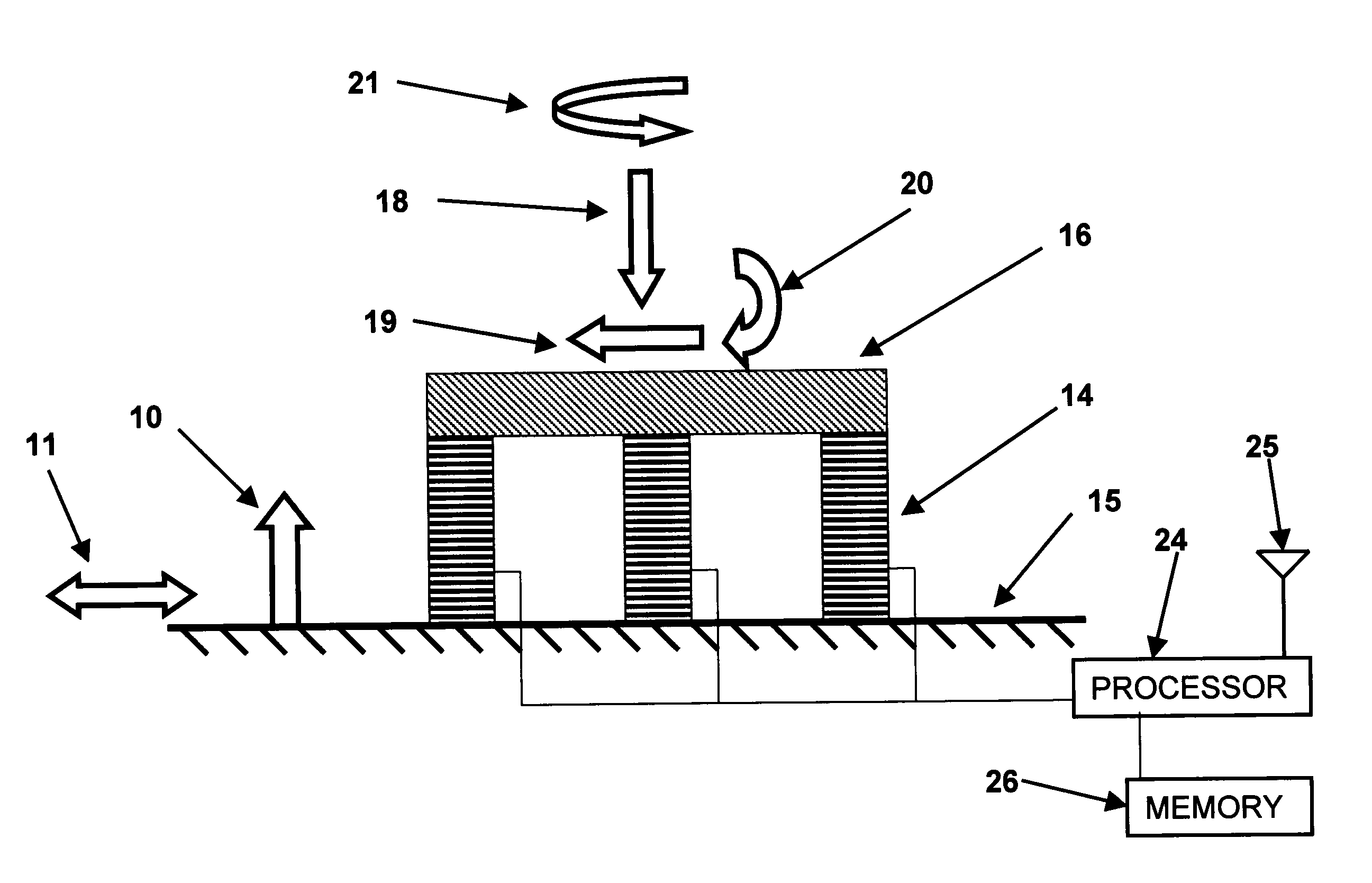
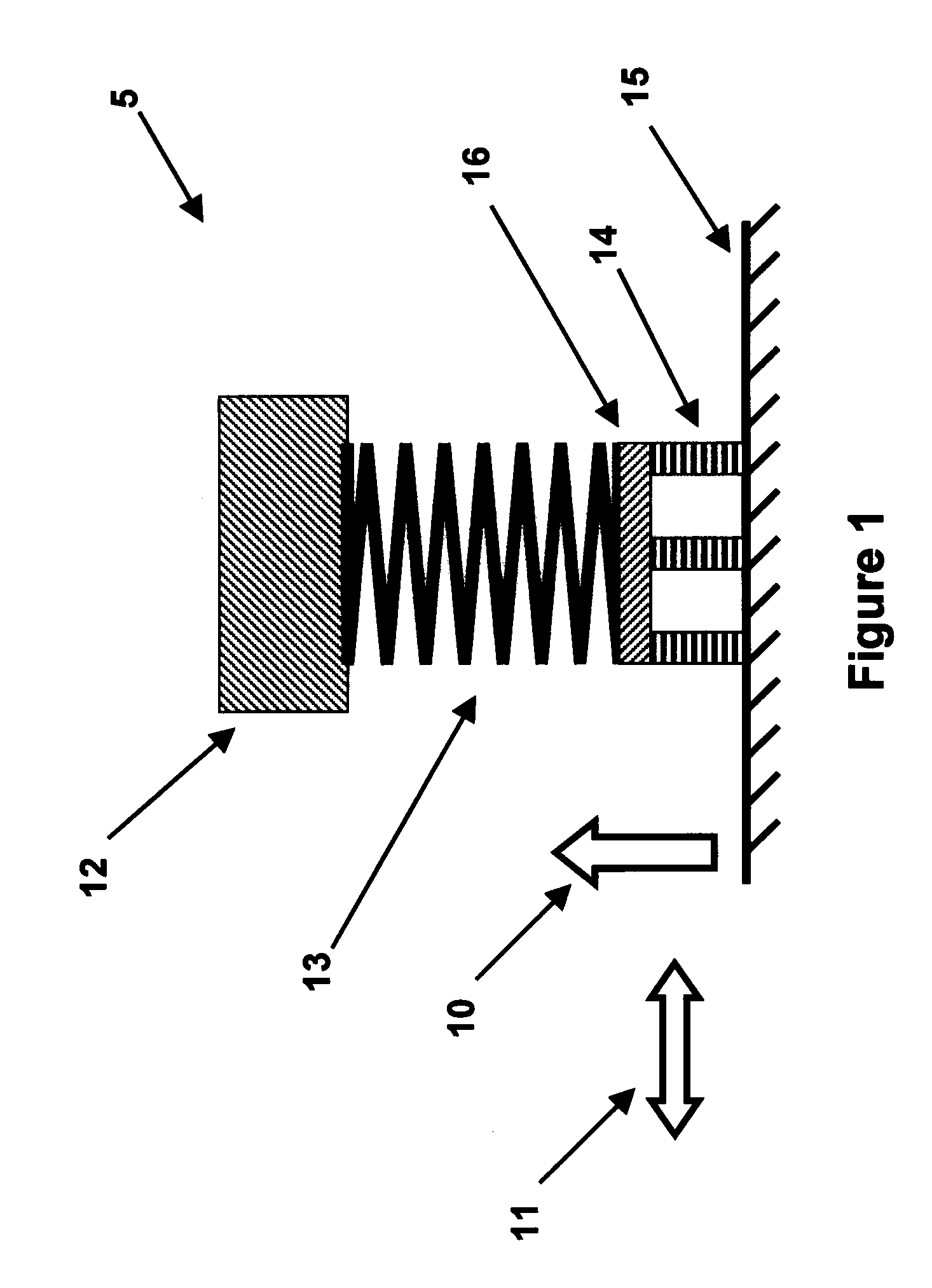
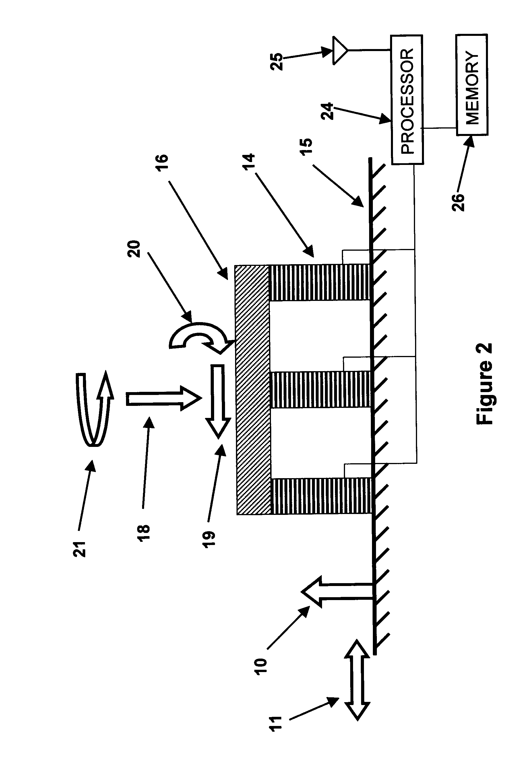
[0019]In the methods and apparatus disclosed herein, the spring end of a mass-spring unit is attached to a housing (support) unit via one or more piezoelectric elements, which are positioned between the spring end of the mass-spring and the housing unit. A housing is intended to mean a support structure, which partially or fully encloses the mass-spring and piezoelectric elements. On the other hand, a support unit may be positioned interior to the mass-spring and / or the piezoelectric elements or be a frame structure that is positioned interior and / or exterior to the mass-spring and / or piezoelectric elements. The assembly can be provided with the means to preload the piezoelectric element in compression such that during the operation of the power generation unit, tensile stressing of the piezoelectric element is substantially avoided. The entire assembly is in turn attached to the base structure (e.g., gun-fired munitions). When used in applications that subject the power generation ...


PUM


Abstract

A method for generating electrical power from an acceleration of an object is provided. The method including: vibrating a mass-spring unit upon an acceleration of an object; transmitting a force resulting from the acceleration from the mass-spring unit to the one or more piezoelectric elements; converting the vibration of the mass-spring unit to an electrical energy; and calculating at least one of the force and acceleration based on an output of the one or more piezoelectric elements.

Description

BACKGROUND OF THE INVENTION[0001]1. Field of the Invention[0002]The present invention relates generally to power supplies, and more particularly, to power supplies for projectiles fired by gun, mortars and the like, which generate power due to an acceleration of the projectile.[0003]2. Prior Art[0004]All existing and future smart and guided projectiles and those with means of one-way or two-way communications with a command or tracking station or with each other require electric power for their operation. In addition, as munitions are equipped with the means of communicating their type and characteristics with the firing system to ensure that the intended round is being used and for fire control purposes, and for health monitoring and diagnostics runs before loading, they would require a low level of power supply minutes and sometimes even seconds before being loaded into the gun system. The amount of power required for the proper operation of such smart and guided munitions or thos...

Claims


Application Information

Patent Timeline
IPC IPC(8): G01P15/09H02N2/18
CPCF42C11/008H02N2/18G01P15/09F42C11/02
Inventor RASTEGAR, JAHANGIR S.SPINELLI, THOMAS
Owner OMNITEK PARTNERS LLC
Why Eureka
Try Eureka