
Pneumatic Tire

a technology of pneumatic tires and cylinders, applied in the field of pneumatic tires, can solve the problems of easy uneven wear and damage to the tip of the tire, and achieve the effect of reducing the noise level of air columnar resonance and the same uneven wear resistance property

Active Publication Date: 2010-09-23
TOYO TIRE & RUBBER CO LTD
View PDF8 Cites 8 Cited by
  • Summary
  • Abstract
  • Description
  • Claims
  • Application Information

AI Technical Summary

Benefits of technology

[0007]The tip part of the acute angle portion is chamfered in the above tire, thereby increasing flow velocity of the air flown in the groove, which results in increased air columnar resonance noise. On the other hand, an attempt to reduce air columnar resonance noise requires that chamfer amount be reduced and as a result, it becomes difficult to suppress the occurrence of uneven wear.
[0008]Therefore, the object of the present invention is to reduce the level of air columnar resonance noise while maintaining uneven wear resistance performance in the pneumatic tire provided with land portions each having an acute angle portion.Means for Solving the Problems
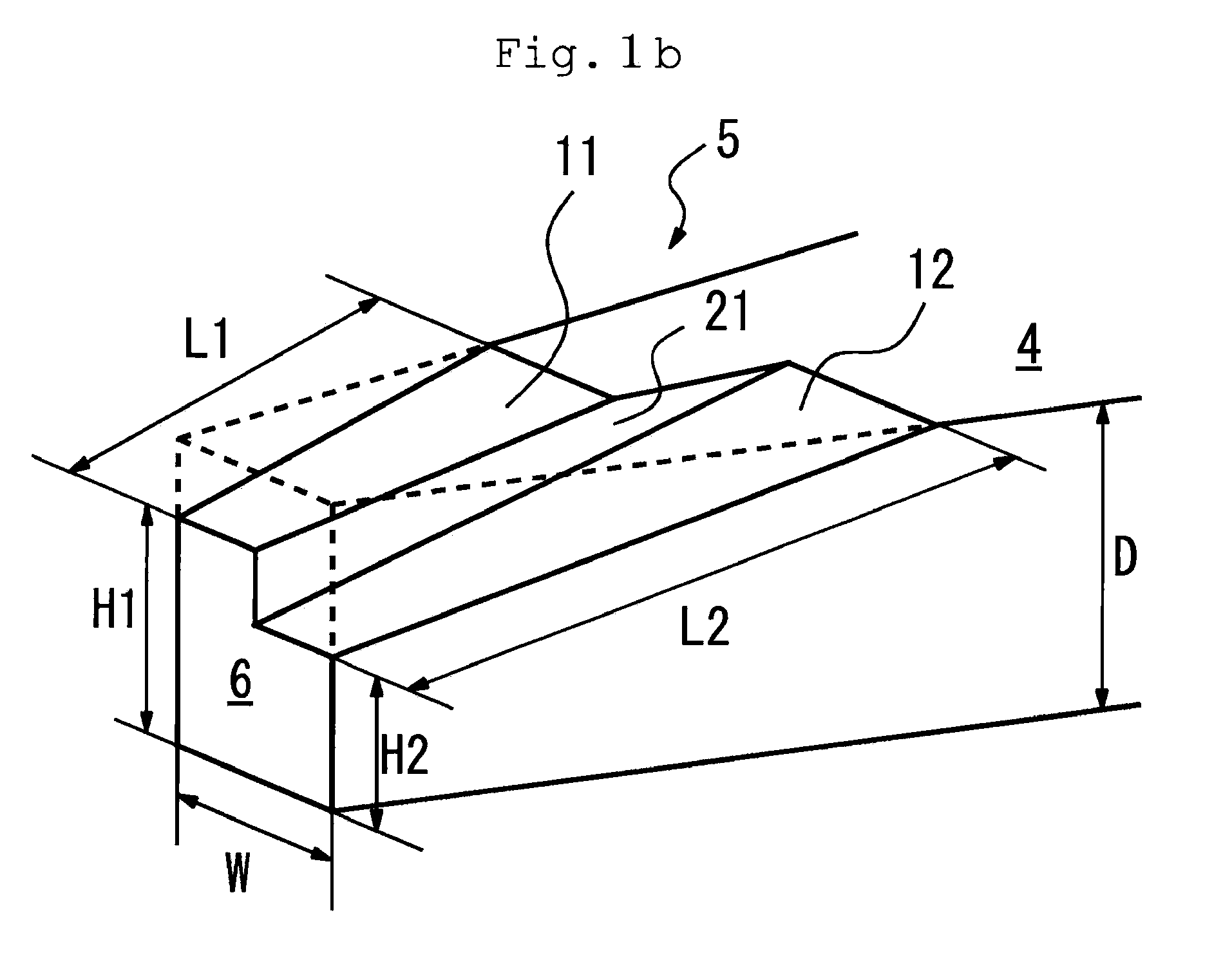
[0010]If the volume of the chamfered portion is the same compared with a case where the acute angle portion is chamfered by one surface, the pneumatic tire has the same uneven wear resistance property. In addition, since the acute angle portion is chamfered by a plurality of chamfered surfaces each having a different height, wherein a step shape is formed by the chamfered surfaces and connecting surfaces that connect the adjacent chamfered surfaces, air flow in the grooves is disturbed by the step shape. As a result, air columnar resonance noise level can be reduced.

Problems solved by technology

Since the acute angle portion of the land portion has low rigidity, a tip part thereof is subject to damage such as chips, tearing and the like.
Even if it was not damaged, uneven wear would easily occur due to the low rigidity.

Method used


Image

  • Pneumatic Tire
  • Pneumatic Tire
  • Pneumatic Tire

Examples


example

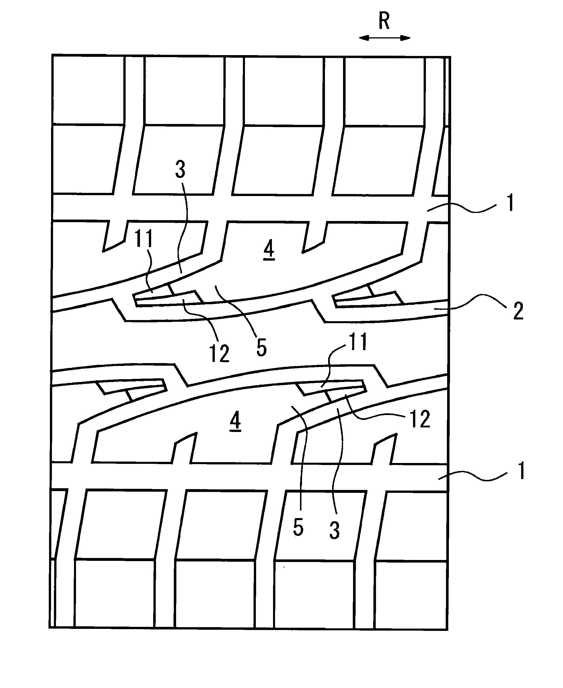
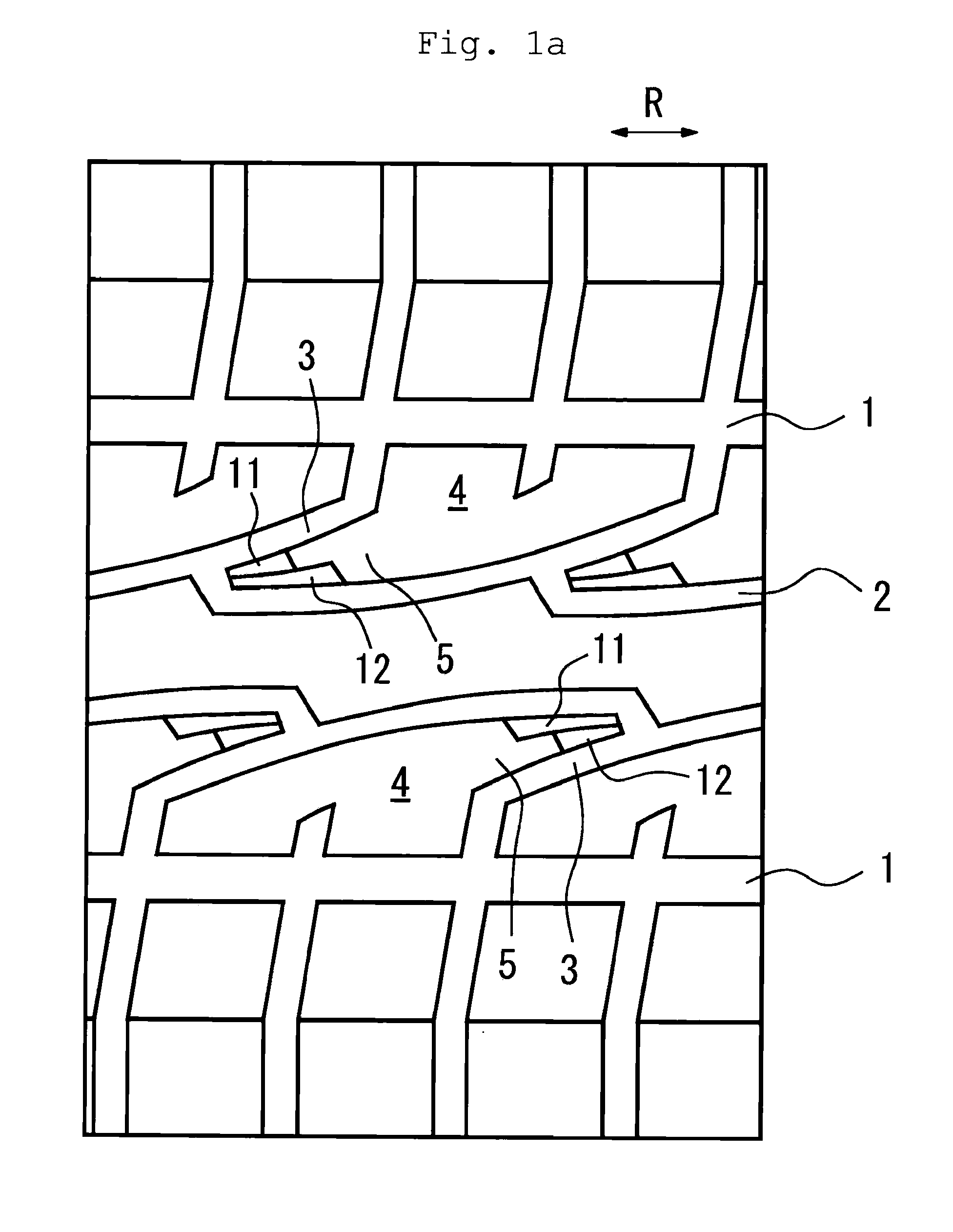
[0036]Tires of Examples and Comparative examples according to the present invention were manufactured and evaluated, respectively. Tires of Examples have a pattern as shown in FIG. 1a. The tires of Examples 1 to 4 comprise acute angle portions as shown in FIG. 1b and those of Examples 5 to 7 comprise acute angle portions as shown in FIG. 3, respectively. The tires of Comparative Examples comprise a pattern as shown in FIG. 4a and acute angle portions chamfered by one chamfered surface 30, as shown in FIG. 4b. In the tires of Comparative Examples 1 and 2, the acute angle portions are chamfered by one chamfered surface having chamfer height H1 and chamfer length L1 of Examples 1 and 2, respectively. Evaluation was made on tires having a tire size of LT265 / 75R16 at an air pressure of 420 kPa. Any dimension of the acute angle portion, which is shown in Table 1, is expressed in ratio relative to the groove depth D.

[0037]In Table 1, air columnar resonance noise represents the value obtain...


PUM


Abstract

A pneumatic tire comprises grooves 1 to 3 formed in a tread and land portions 4 each having an acute angle portion 5 formed by the grooves 2 and 3. The acute angle portion 5 is chamfered by a plurality of chamfered surfaces 11 and 12 to form into a step shape by the chamfered surfaces 11 and 12 and a connecting surface 21 that connects the adjacent chamfered surfaces 11 and 12. Furthermore, from one sidewall to the other sidewall of the acute angle portion 5 at an end 6 of the acute angle portion 5, a height H1 of the chamfered surface 11 and a height H2 of the chamfered surface 12 are gradually decreased while a length L1 of the chamfered surface 11 and a length L2 of the chamfered surface 12 are gradually increased.

Description

TECHNICAL FIELD[0001]The present invention relates to a pneumatic tire with grooves formed in its tread and provided with land portions each having an acute angle portion. More particularly, it relates to a pneumatic tire with reduced air columnar resonance noise level while maintaining uneven wear resistance performance.[0002]This application claims benefit of priority based on Japanese Patent Application No. 2007-288198 filed on Nov. 6, 2007, the entire same contents of which are incorporated by reference herein.BACKGROUND ART[0003]In a pneumatic tire, land portions are formed by a plurality of grooves formed in a tread. In order to achieve the desired performance, the land portion may be provided with an acute angle portion. For example, a portion sandwiched between two inclined grooves forms an acute angle portion in the pneumatic tire disclosed in Patent Document 1.[0004]Since the acute angle portion of the land portion has low rigidity, a tip part thereof is subject to damage ...

Claims


Application Information

Patent Timeline
Patent Type & Authority Applications(United States)
IPC IPC(8): B60C11/03B60C11/117
CPCB60C11/0302B60C11/0306B60C11/1392B60C11/1384B60C11/13
Inventor MIYAZAKI, TETSUJI
Owner TOYO TIRE & RUBBER CO LTD
Learn More