Rewinding method and rewinding machine that carries out this method

a rewinding machine and rewinding method technology, applied in the direction of transportation and packaging, thin material processing, article delivery, etc., can solve the problems of affecting the final quality of the product, the amount of glue sprayed on the tubular cardboard core can be too much, and the risk of paper web soaking too much

Inactive Publication Date: 2010-09-23
MTC MACCINE TRASFORMAZIONE CARTA SRL
View PDF11 Cites 27 Cited by
  • Summary
  • Abstract
  • Description
  • Claims
  • Application Information

AI Technical Summary

Benefits of technology

[0016]It is therefore a feature of the present invention to provide an improved rewinding machine that allows the distribution of glue near the tear line or clean cut line in an effective way for completing a log and starting a new one.

Problems solved by technology

However, such glue distribution systems have relevant drawbacks concerning the final quality of the products.
In particular, the amount of glue sprayed on the tubular cardboard core can be too much so that iy risks to soak too much the paper web during the contact of the core with the roller.
Furthermore, this contact dirties the winding roller and can cause the paper to stick on the upper roller instead of the core.
Furthermore, in case of a delay of the new core with glue entering the winding zone, the glue can dry loosing its effect.
This would cause a maintenance stop of the machine for removing the core and putting in a new one, with loss of time and reduced production rate.
However, the free end gluing unit, as well as the gluing step of the starting end of the log, create relevant problems.
Therefore the final closure is often faulty, with presence of large wrinkles and, in particular, of free end portions folded on them.
However, this system is not very reliable, since a slip of the core and therefore a subsequent loss of rotational speed of the core determines an incorrect distribution of the glue causing, for example, the free end not to stick to the roll, or in particular, a faulty start of the new winding cycle.
An inaccurate movement of the core in the cradle, or a not controlled position of the web of paper owing to the contact of the core with the web can, in fact, affect the application of the glue on the paper at predetermined points, causing the core to jam in the cradle and obliging a maintenance stop.
This causes loss of time with reduced production rate and increase of costs.

Method used


Image

  • Rewinding method and rewinding machine that carries out this method
  • Rewinding method and rewinding machine that carries out this method
  • Rewinding method and rewinding machine that carries out this method

Examples


Embodiment Construction

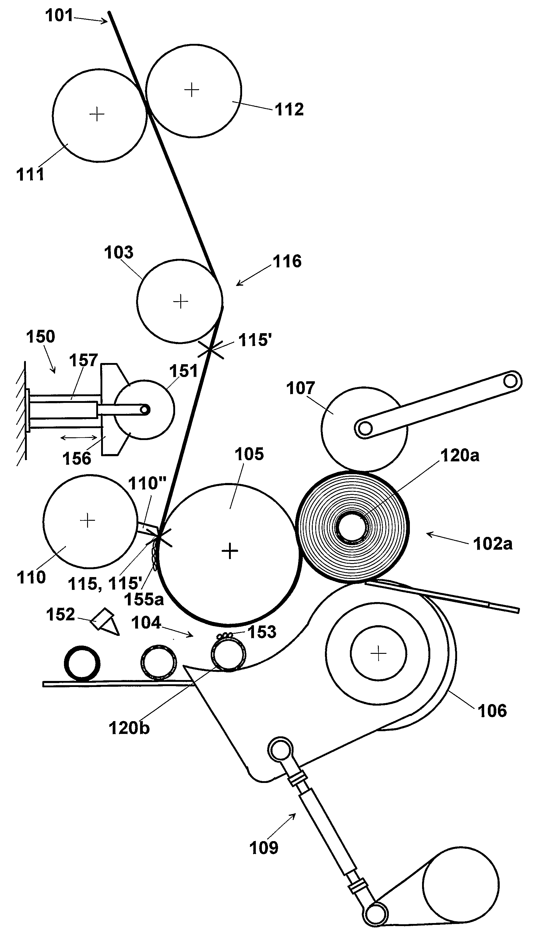
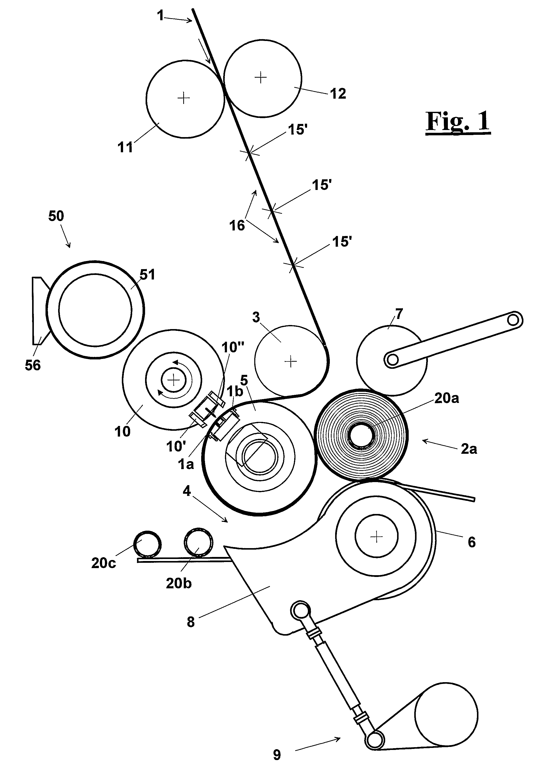
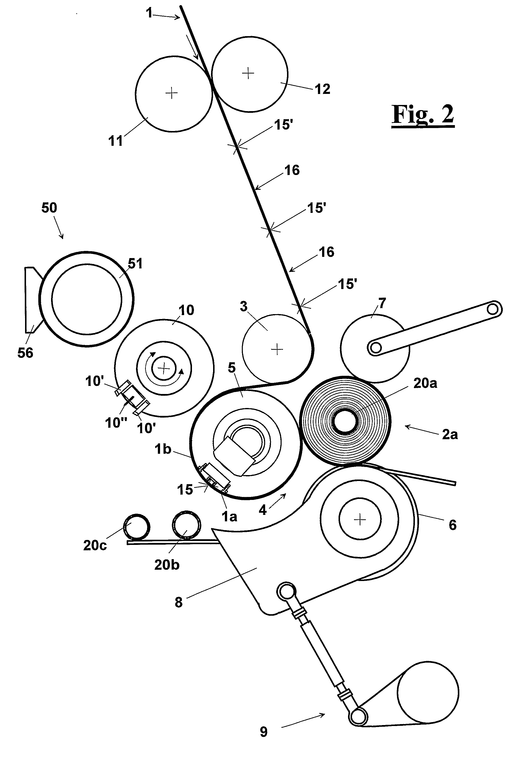
[0075]With reference to FIGS. 1 to 5, a rewinding apparatus machine of a paper web 1 for making a log 2a comprises a feed roller 3 of web 1 and, downstream of it, a winding cradle 4, in which the production of log 2a is carried out for winding web 1 about a core 20.

[0076]The latter is supplied into cradle 4 by suitable introduction means, for example a loading unit that draws the cores 20 from a chute guide, not shown in the figures. Alternatively, in a way not shown but known to a skilled person, a log can be formed without a core. In this case, the web is wound on itself to start forming a new log that then is wound in cradle 4.

[0077]Cradle 4, according to the prior art, comprises a upper winding roller 5, a lower winding roller 6 and a pressure roller 7, which follows the growth of log 2a with the object of assuring its continuous contact with winding rollers 5 and 6, for controlling its progressive diameter growth.

[0078]Upstream from feed roller 3, instead, a perforation roller ...


PUM

PropertyMeasurementUnit
lengthaaaaaaaaaa
timeaaaaaaaaaa
diameteraaaaaaaaaa

Abstract

Rewinding method and rewinding machine of a paper web (1) for making a log (2a) comprising a feed roller (3) for feeding the web (1) and a winding cradle (4) in which a log (2a) is formed winding the paper web (1) about a core (20). The latter is supplied into the cradle (4) by introduction means by a loading unit that draws the cores (20) from a chute guide. Upstream from the feed roller (3) a perforation roller (11) is provided that acts in combination with a counter-roller (12) to make a plurality of transversal tear lines (15′) on the paper web (1) forming a plurality of panels (16) connected to each other united by the tear line. Upstream from the means for introducing the core (20), furthermore, a gluing means is provided (50) for application of a measured amount of glue (55) on a determined portion of the paper web (1), in particular upstream from (Ia), down-stream of (Ib), or bridging the tear line or clean cut (15). Such lines are made by cutting means, which make either a tear line or clean cut (10″), in coincidence or direct vicinity with the gluing means for applying the glue (50, 10′). The gluing means (50) can, for example, provide a pad (10′) that receives the glue by a gluing roller (51).

Description

FIELD OF THE INVENTION[0001]The present invention relates to an improved rewinding method for making logs of paper from a paper web and that is used, for example, for the production of rolls of toilet paper, rolls of all purpose tissue paper for household use, non woven fabric, paper industrial rolls and the like.[0002]Furthermore the invention relates to an improved rewinding machine that carries out this method.BACKGROUND OF THE INVENTION[0003]Rewinding machines are known where the winding step takes place in a special winding zone that comprises an upper roller, a lower roller and a pressing roller.[0004]In particular, in EP1232980 a core of cardboard, which is located on a special movable support cradle, is brought into contact with the upper winding roller and is therefore dragged into a winding zone, wherein glue is previously spread on the surface of the tubular core, to let the paper web to remain stuck to the core and start winding the log.[0005]To this purpose, glue distri...

Claims


Application Information

Patent Timeline
Patent Type & Authority Applications(United States)
IPC IPC(8): B65H19/28B65H19/26B65H19/30B65H35/04B65H35/10
CPCB65H19/2269B65H19/286B65H2408/235B65H2301/414421B65H19/29
Inventor DE MATTEIS, ALESSANDRO
Owner MTC MACCINE TRASFORMAZIONE CARTA SRL
Why Eureka
Try Eureka