Motion conversion device

a technology of rotational magnetic and motor, which is applied in the direction of dynamo-electric machines, electrical apparatus, propulsion systems, etc., can solve the problems of limited success inability to achieve rotational movement in the motor, and general inefficiency of permanent magnet motors, etc., to achieve simple and feasible operation, increase the working power of the motor, and improve the effect of the working efficiency

Inactive Publication Date: 2010-09-23
LAWSON WILLIAM J
View PDF3 Cites 7 Cited by
  • Summary
  • Abstract
  • Description
  • Claims
  • Application Information

AI Technical Summary

Benefits of technology

[0004]It is an object of the present invention to provide a practical, self-starting, permanent magnet, rotational motor capable of performing significant work through a rotational shaft or like drive assembly.
[0005]It is a further object of the present invention to provide a permanent magnet motor whose circumferential stator magnet segments and rotor assembly magnets can be multiplied to increase the working power of the motor.
[0006]It is still another object to provide a permanent magnet motor that will operate efficiently with state-of-the-art permanent magnets including ferrite magnets, magnets formed of ceramics, and other existing and future improved permanent magnets.
[0007]It is another object of the present invention to provide a permanent magnet motor and integrated rotor magnet movement control system that is relatively simple and feasible from a manufacturing cost standpoint.
[0008]The difficulties associated with prior permanent magnet rotational motors can be completely overcome and a fully workable permanent magnet rotary motor of a self-starting nature can be achieved. Essentiall

Problems solved by technology

In the past, permanent magnet motors have met with only limited success in that they have not been self-starting and, hence, have routinely been operable only as linear motors or actuators and not as rotational devices.
In fact, permanent magnet motors generally tend to be unworkable or very inefficient due to difficul

Method used


Image

  • Motion conversion device
  • Motion conversion device
  • Motion conversion device

Examples


Embodiment Construction

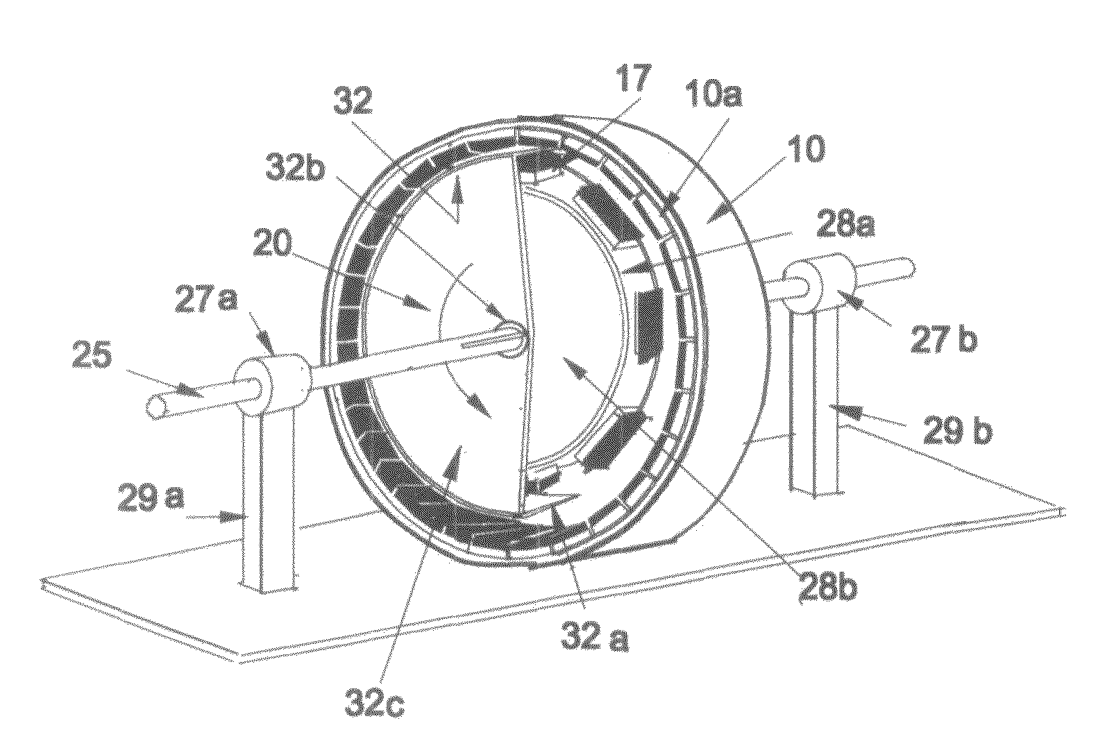
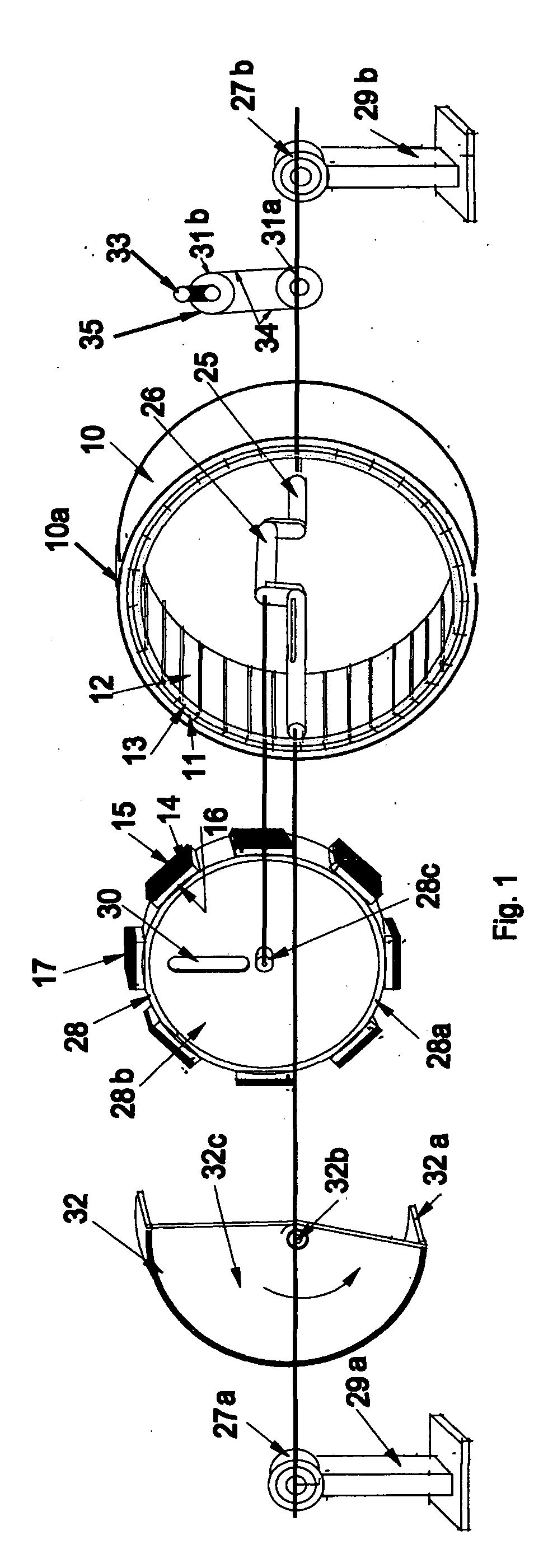
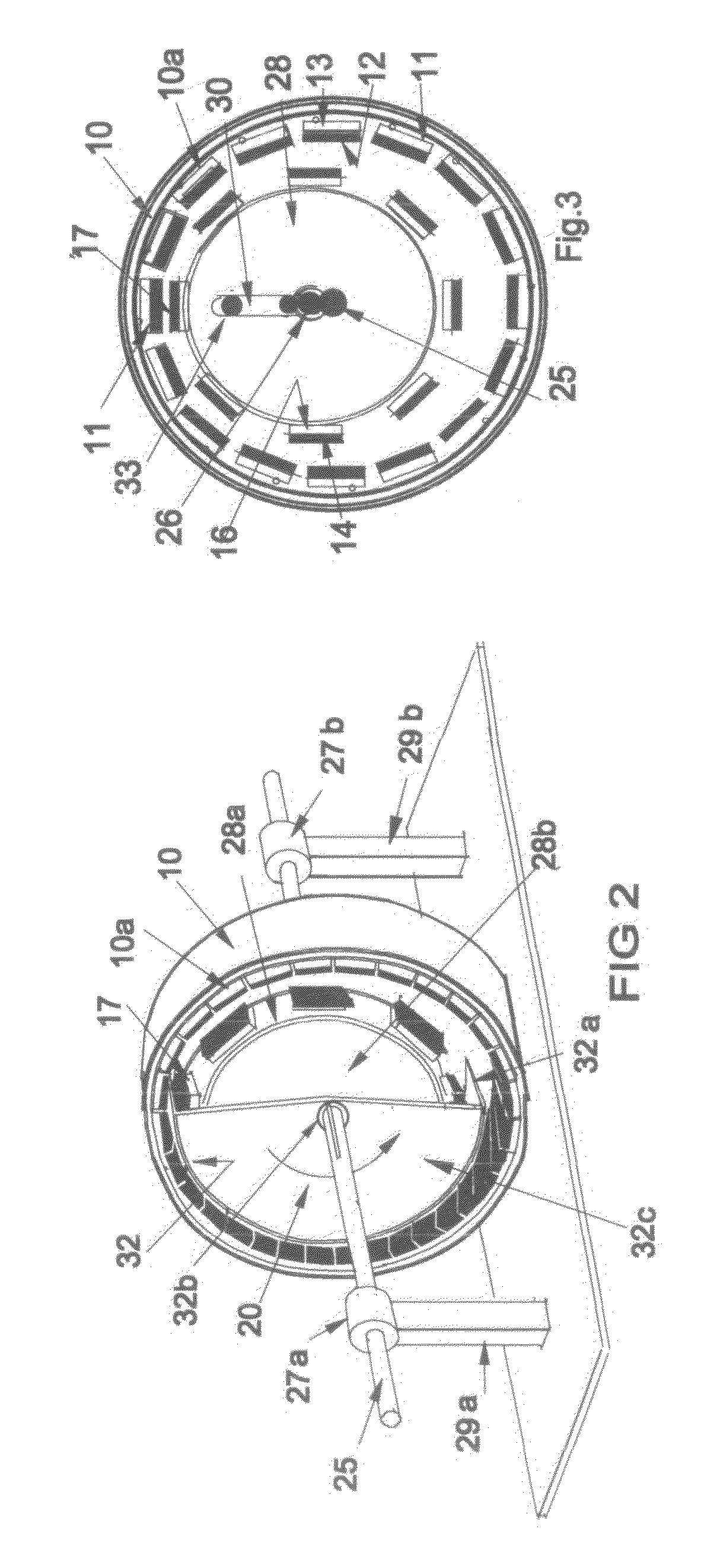
[0014]Referring to the drawings and initially to FIG. 1, the components of the motion conversion device, or the permanent magnetic rotational motor of the present invention are shown in isometric views and in exploded fashion. Iron band member 32 comprises an arcuate band component 32a with offset crankshaft attachment point 32b and protective wall 32c. Iron band member 32 is configured to rotate in the direction designated by arrow 20, shown in FIGS. 2, 4-7.

[0015]Rotor assembly 28 is circular in configuration, comprising circular outer wall 28a, protective wall 28b, journal attachment point 28c, and slot 30. Rotor magnets 14 on outer wall 28a circumscribe rotor assembly 28. Master rotor magnet 17 is positioned on the uppermost surface of wall 28a. Each rotor magnet 14, as well as master rotor magnet 17, has polarized faces 15 and 16, north and south poles, respectively.

[0016]Stator 10 is an annular body with a ring shaped outer wall 10a. Attached to and circumferentially extending ...


PUM


Abstract

A permanent magnet rotational motor employs the use of a rotating iron band member which absorbs the magnetic flux of both of the opposing magnet flux fields from stator and rotor magnets. This causes mutually opposing, interacting magnetic flux fields of the rotor and stator magnets to enter in close proximity to one another without opposition. This results in the two interacting fields remaining totally one within the other, until the iron band member between the two interacting fields is rotably extracted, compelling the two interacting opposing flux fields to repel each other and causing the rotor assembly to push the power assembly crankshaft in the desired direction. In this manner the aforementioned repelling and attracting effects between the interacting fields experienced in the prior art, which negates rotation in permanent magnet motors, is eliminated. The present invention also provides a device to maintain the necessary coactive relationship between the opposing magnetic fields of rotor and stator magnets throughout a complete rotational cycle of the permanent magnet motor.

Description

BACKGROUND OF THE INVENTION[0001]This invention is related to the field of rotational magnetically powered motors.[0002]In the past, permanent magnet motors have met with only limited success in that they have not been self-starting and, hence, have routinely been operable only as linear motors or actuators and not as rotational devices. In fact, permanent magnet motors generally tend to be unworkable or very inefficient due to difficulties relating to the entering and exiting of one magnetic field into and from another magnetic field, resulting from magnetic repulsion or attraction between interacting fields. Such magnetic cancelling or neutralizing effects make rotational movement in the motor impossible to achieve or negligible, if achieved at all.SUMMARY OF THE INVENTION[0003]It is thus an object of the present invention to overcome the limitations and disadvantages of prior permanent magnet rotational motors.[0004]It is an object of the present invention to provide a practical,...

Claims


Application Information

Patent Timeline
IPC IPC(8): H02K7/075
CPCH02K21/38H02K53/00H02K41/065
Inventor LAWSON, WILLIAM J.
Owner LAWSON WILLIAM J
Why Eureka
Try Eureka