Impeller blade

a technology of axial blades and blades, applied in the direction of marine propulsion, vessel construction, other chemical processes, etc., to achieve the effect of maintaining performance parameters and design constraints, and reducing axial width

Inactive Publication Date: 2006-07-04
MINEBEA CO LTD
View PDF40 Cites 7 Cited by
  • Summary
  • Abstract
  • Description
  • Claims
  • Application Information

AI Technical Summary

Benefits of technology

The invention provides an axial flow fan with reduced axial width while maintaining its performance parameters and design constraints. This is achieved by eliminating large electronic circuit components, operating from a starting voltage in the range of about 28V-64V, and employing a housing or a voltage regulator IC as a heat sink. The fan also incorporates a blade with a family of airfoil sections that allow for a reduction in axial width while maintaining a favorable velocity profile and a maximum work distribution between the root and tip portions of the blade. The invention further includes a stator assembly with a core, at least one winding, and a printed circuit board secured to the core and electrically connected to the winding. The fan also includes an impeller with at least thirteen blades coupled to a circular band at the root portion of the blade, a driving motor, a yoke section, and a fan housing. The blade is characterized in plan form wherein it is varied from the root portion to the tip portion with a maximum chord located between the root portion and the tip portion, the leading edge and the trailing edge of the blade are convex from the root portion to the tip portion.

Problems solved by technology

Design constraints include fan size (including axial width), fan weight, motor input power, and acoustic noise signature.

Method used


Image

  • Impeller blade
  • Impeller blade
  • Impeller blade

Examples


Embodiment Construction

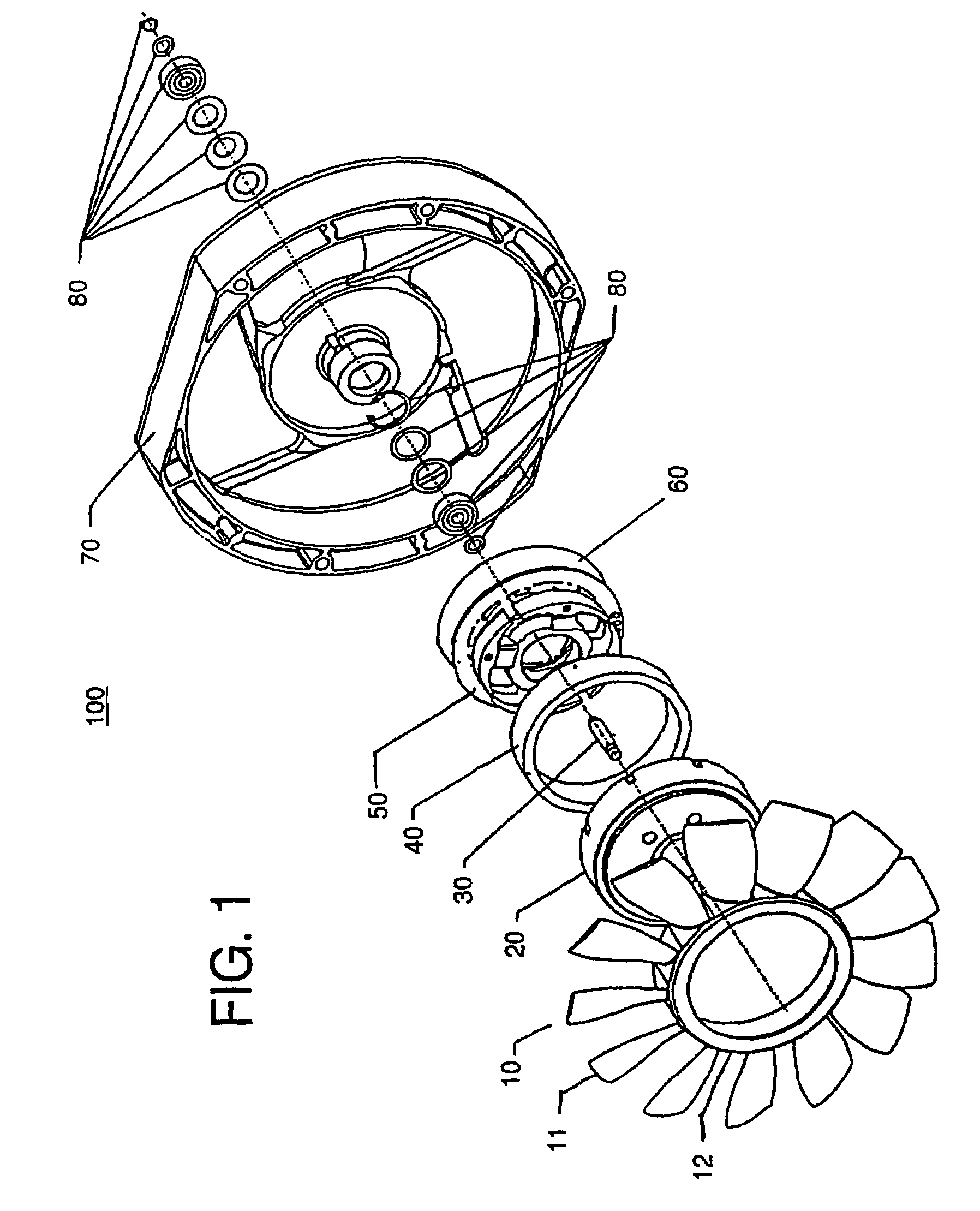
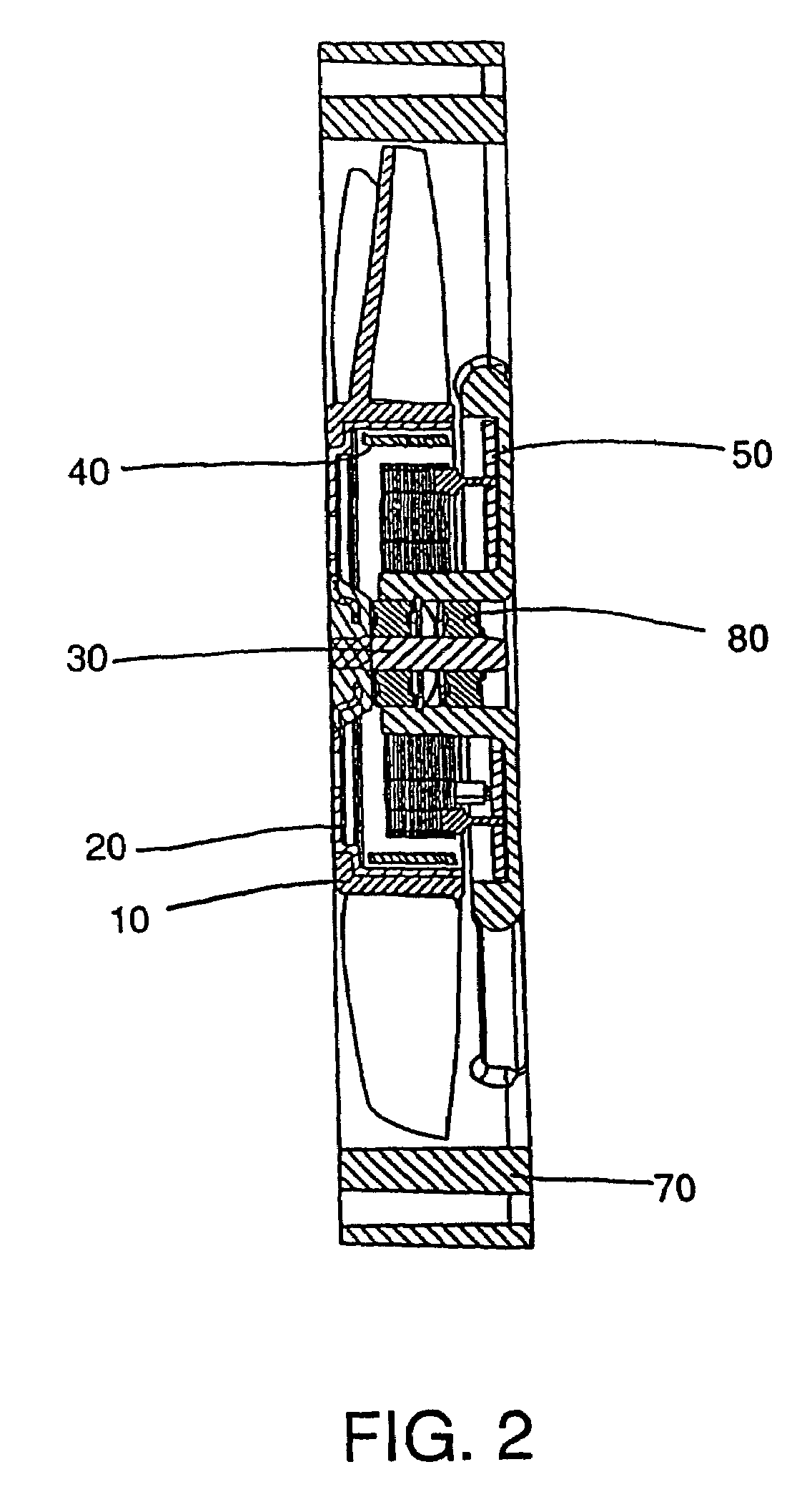
[0050]Referring now to the drawings, and in particular to FIGS. 1 and 2, wherein illustrated is an axial flow fan 100, comprising an impeller 10, embodying a preferred embodiment of the present invention for generating airflow when rotated, a yoke 20 mounted in impeller 10, a shaft 30 coupled to yoke 20, a permanent magnet 40 mounted in yoke 20, a stator assembly 50, a fan housing 70, an insulation sheet 60 for electrically insulating the base within stator assembly 50 from fan housing 70, and bearings and mounting hardware 80 which serve to secure the shaft 30 to housing 70 while allowing shaft 30 to freely rotate, thereby rotating impeller 10. The impeller 10 comprises a plurality of blades 11 equally spaced and circumferentially mounted on circular band 12. The permanent magnet 40 mounted in yoke 20, when combined with stator assembly 50, forms an electrical motor which turns impeller 10 when a voltage is applied to an exciting circuit on the printed circuit board within stator a...


PUM


Abstract

Impeller blades and a method for designing impeller blades wherein the blades comprise a plurality of specially designed airfoil sections, each section having along substantially the entire length thereof, a cross-sectional shape characterized by a maximum thickness located substantially constantly between about 16% chord to about 23% chord and a maximum camber located substantially constantly between about 40% chord to about 51% chord. The blades are designed so that the axial width of the blades is decreased while maintaining performance parameters and design constraints.

Description

[0001]This application is made under 37 C.F.R. § 1.53 (b) and is a Continuation of Prior Application No. 10 / 222,562 filed on Aug. 16, 2002 now U.S. Pat. No. 6,616,409 which is a continuation of 09 / 624,583 filed Jul. 24, 2000 now U.S. Pat. No. 6,457,953 which is a continuation of 09 / 118,843 filed Jul. 20, 1998 which issued as U.S. Pat. No. 6,129,528 on Oct. 6, 2000.FIELD OF THE INVENTION[0002]The present invention relates to an axial flow fan, and more particularly to an improved printed circuit board and fan housing, and improved blades comprising a new airfoil family having the advantages of decreasing the axial width of the axial flow fan while maintaining its performance parameters and design constraints. The axial flow fan of the present invention is especially suitable for use in cooling electronic components.BACKGROUND OF THE INVENTION[0003]A conventional axial flow fan is generally composed of a driving motor, a cylindrical central hub section, a plurality of blades, and a ho...

Claims


Application Information

Patent Timeline
Patent Type & Authority Patents(United States)
IPC IPC(8): F01D5/14F04D29/38H02K7/14H02K11/00H02K11/04H02K29/00
CPCF04D29/384H02K11/0073H02K7/14Y10S416/05H02K29/00Y10S416/02H02K11/33
Inventor BRADBURY, PHILLIP JAMESNGUYEN, PHEP XUANJENKINS, JR., CHALMERS R.
Owner MINEBEA CO LTD
Why Eureka
Try Eureka