Stereoscopic display device

a display device and stereoscopic technology, applied in the direction of lenses, instruments, optical elements, etc., can solve the problems of insufficient separation of parallaxes, inability to obtain efficient lens effect, and inability to achieve favorable three-dimensional display visibility, etc., to achieve good visibility, good visibility, and good visibility

Inactive Publication Date: 2010-09-23
SONY CORP
View PDF5 Cites 27 Cited by
  • Summary
  • Abstract
  • Description
  • Claims
  • Application Information

AI Technical Summary

Benefits of technology

[0018]It is desirable to provide a stereoscopic display device capable of achieving an efficient lens effect in which a polarization property of a liquid crystal lens is considered, and thus performing three-dimensional displaying having good visibility.
[0027]According to the stereoscopic display device of the embodiment (3) of the invention, only the light component which is in the direction parallel with the predetermined orientation direction of the liquid crystal molecules of the lens array element is caused to transmit by the polarizer. Thus, the efficient lens effect in which the polarization property of the liquid crystal lens is considered is obtainable. Therefore, it is possible to perform the three-dimensional displaying having good visibility.

Problems solved by technology

Thus, in a case where a stereoscopic display device is structured by combining the liquid crystal display with the liquid crystal lens array element, an efficient lens effect may not be obtained when the polarization property of the liquid crystal display and the polarization property of the liquid crystal lens array element are not considered, since both of them have their polarizing properties.
When the efficient lens effect is not obtained, favorable visibility of three-dimensional displaying may not be acquired.
For example, a plurality of parallaxes may not be separated sufficiently, and thus a stereoscopic image may be seen blurred or unclear.
However, influence of the polarization property of the liquid crystal lens array element described above (i.e., a polarization direction in which the lens effect is generated as the liquid crystal lens) has not been considered in structuring the stereoscopic display device.

Method used


Image

  • Stereoscopic display device
  • Stereoscopic display device
  • Stereoscopic display device

Examples


first embodiment

[Overall Configuration of Stereoscopic Display Device]

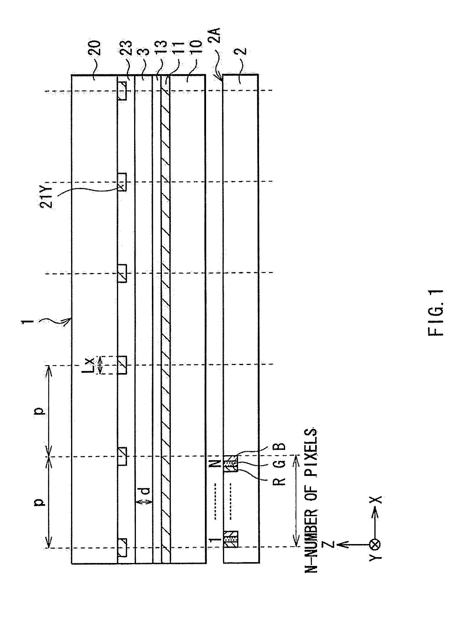
[0060]FIG. 1 illustrates one example of a configuration of a stereoscopic display device according to a first embodiment of the invention. The stereoscopic display device is provided with a display panel 2 for performing image-displaying two-dimensionally, and a lens array element 1 disposed to oppose a display screen 2A of the display panel 2. The stereoscopic display device is configured to be capable of switching over between two displaying modes including a two-dimensional displaying mode and a three-dimensional displaying mode. As will be described later in greater detail, the lens array element 1 is a variable lens array utilizing liquid crystal lenses, and is capable of performing ON and OFF control of a lens effect electrically. The lens array element 1 controls the lens effect according to the displaying mode, so as to selectively change a passing state of light rays from the display panel 2. The display panel 2 performs...

second embodiment

[0085]Now, a second embodiment of the invention will be described. Note that the same or equivalent elements as those of the first embodiment described above are denoted with the same reference numerals, and will not be described in detail.

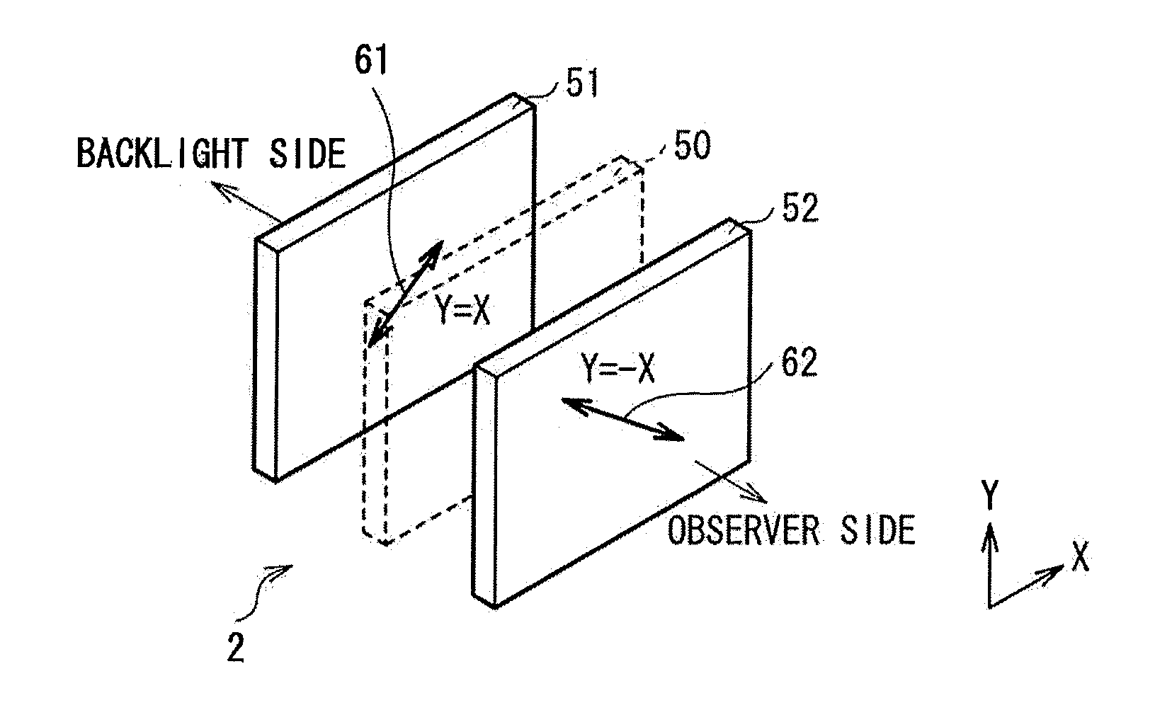
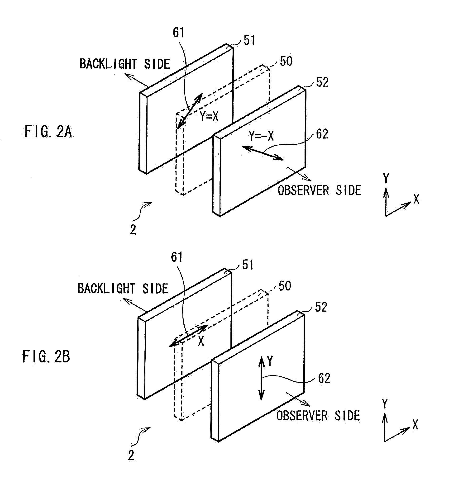
[0086]In the first embodiment described above, the polarization direction of the display-image light exit from the display panel 2 and the polarization direction 63 having the lens effect of the lens array element 1 are configured to be parallel to each other. The present embodiment provides an improvement in a case where the polarization direction of the display-image light and the polarization direction 63 having the lens effect do not match with each other. It is to be noted that, in a stereoscopic display device according to the present embodiment, only a relationship between the polarization direction of the display panel 2 and the polarization direction of the lens array element 1 differs from the first embodiment described above, and the ba...

third embodiment

[0092]Now, a third embodiment of the invention will be described. Note that the same or equivalent elements as those of the first embodiment described above are denoted with the same reference numerals, and will not be described in detail.

[0093]In the first embodiment described above, the polarization direction of the display-image light exit from the display panel 2 and the polarization direction 63 having the lens effect of the lens array element 1 are configured to be parallel to each other. The present embodiment provides an improvement in a case where the polarization direction of the display-image light and the polarization direction 63 having the lens effect do not match with each other. It is to be noted that, in a stereoscopic display device according to the present embodiment, only a relationship between the polarization direction of the display panel 2 and the polarization direction of the lens array element 1 differs from the first embodiment described above, and the bas...


PUM


Abstract

A stereoscopic display device includes: a display panel having a display screen on which two-dimensional image is displayed, and configured to polarize image light of the image-displaying into a particular polarization direction; and a lens array element disposed to oppose the display screen of the display panel, and having a liquid crystal layer which includes liquid crystal molecules having a refractive index anisotropy and aligned in a predetermined orientation direction under no application of voltage. The lens array element is configured to electrically change the alignment of the liquid crystal molecules to generate a lens effect, and configured to selectively change a state of passing therethrough of the image light exiting from the display panel. The predetermined orientation direction of the liquid crystal molecules of the lens array element and the polarization direction of the image light are parallel to each other.

Description

BACKGROUND OF THE INVENTION[0001]1. Field of the Invention[0002]The present invention relates to a stereoscopic display device capable of electrically switching over between two-dimensional displaying and three-dimensional displaying by using a variable lens-array element utilizing a liquid crystal lens.[0003]2. Description of Related Art[0004]There has been known a binocular stereoscopic display device or a multi-eye stereoscopic display device, which realizes a stereoscopic vision by presenting parallax images, having parallax, to both eyes of an observer, respectively. There is also a spatial-image stereoscopic display device, which realizes more natural stereoscopic vision. The spatial-image stereoscopic display device radiates a plurality of light rays having different radiation directions into a space, to form a spatial image corresponding to a plurality of viewing angles.[0005]As a way of realizing such stereoscopic display devices, there has been known a stereoscopic display...

Claims


Application Information

Patent Timeline
Patent Type & Authority Applications(United States)
IPC IPC(8): H04N13/04G02B30/27G02B30/28
CPCG02B3/14G02B27/2214H04N13/0454H04N13/0404G03B35/24H04N13/305H04N13/359G02B30/27G02B30/28
Inventor TAKAHASHI, KENICHISAKAMOTO, SHOOKU, TAKASHI
Owner SONY CORP
Why Eureka
Try Eureka