Dual Fiber Stretchers for Dispersion Compensation

Inactive Publication Date: 2010-09-23
SOUTHERN PHOTONICS
View PDF6 Cites 17 Cited by
  • Summary
  • Abstract
  • Description
  • Claims
  • Application Information

AI Technical Summary

Benefits of technology

[0007]It is therefore an object of the present invention to provide a system or method for

Problems solved by technology

Fiber optic systems having light propagating in multiple parallel paths, such as interferometers and Wavelength Division Multiplexed (WDM) systems, often suffer from output distortion due to dispersion mismatch between paths.
Dispersion mismatch arises from differences between optical paths such as refractive index, optical fiber manufacturing tolerance and the use of different components.
Dispersion imbalance in an OCT device reduces system resolution due to distortion of the point-spread-function.
Similarly, optical systems employing

Method used


Image

  • Dual Fiber Stretchers for Dispersion Compensation
  • Dual Fiber Stretchers for Dispersion Compensation
  • Dual Fiber Stretchers for Dispersion Compensation

Examples


Embodiment Construction

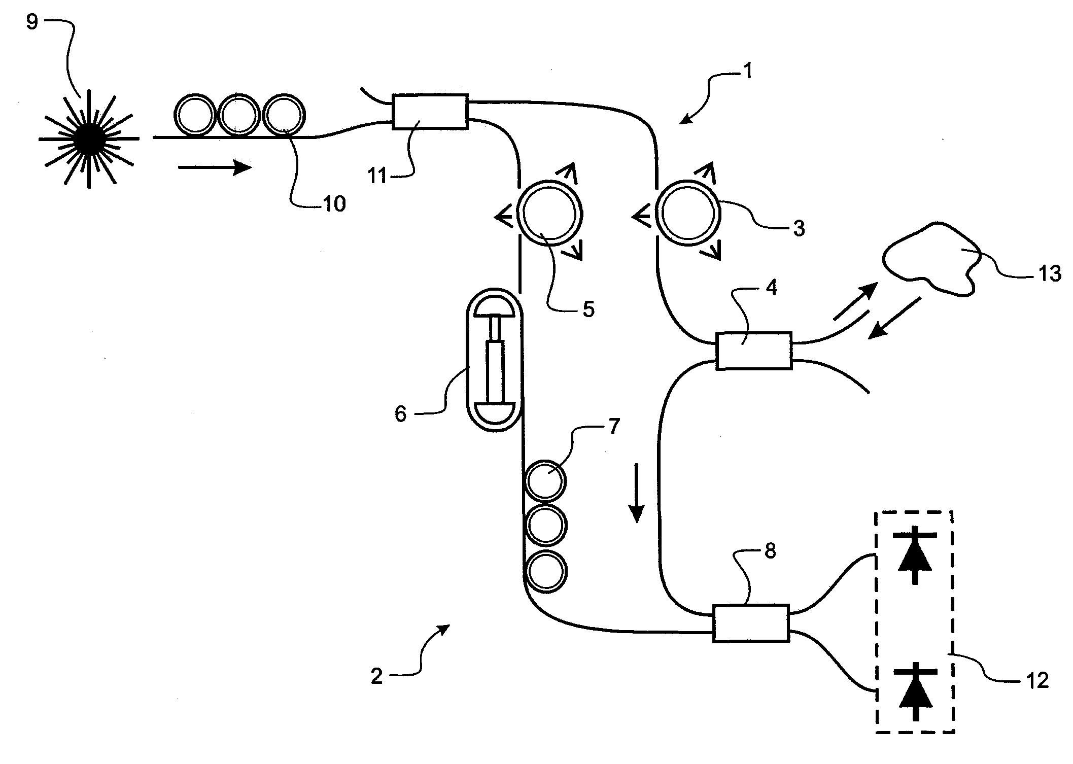
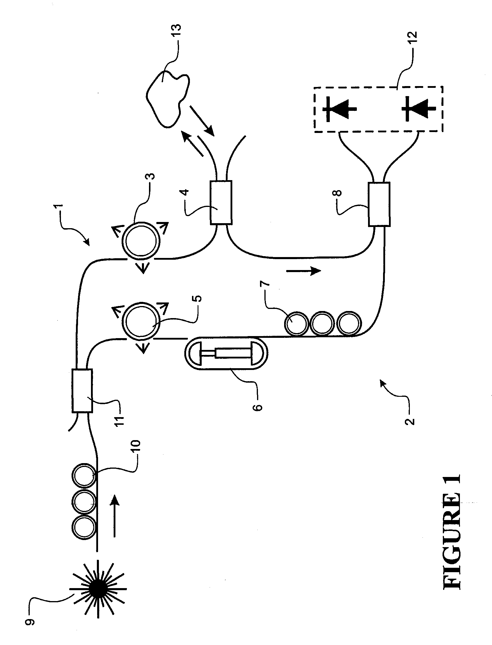
[0062]Optical Coherence Tomography (OCT) is a real-time non-invasive optical imaging technique that can produce high resolution images of biological tissues. The technique is based on low coherence white light interferometry where image slices within the depth of a sample placed in one interferometer arm are obtained by scanning an optical time delay line in the reference arm of the interferometer.

[0063]OCT systems have been implemented in many different interferometer arrangements. Of particular interest is the use of optical fibers and broadband fiber couplers to construct an OCT interferometer. Fiber-based OCT systems present several advantages in terms of compactness, flexibility, and easiness of light distribution to the sample, especially for use in in vivo experiments.

[0064]However, most known fiber-based OCT systems still rely on some optical free-space components to match path lengths, such as an optical delay line. Further, the use of optical fibers has an inherent chromat...


PUM


Abstract

An optical system having at least two waveguides that are deformable to provide adjustments to dispersion and path length.

Description

REFERENCE TO PRIOR APPLICATION[0001]This application claims the benefit of U.S. Provisional Application No. 61 / 122,513, filed Dec. 15, 2008 the entirety of which is incorporated herein by reference.FIELD OF THE INVENTION[0002]The present invention broadly relates to optical fiber based dispersion compensation and in particular to an all fiber based dispersion compensation system used for Optical Coherence Tomography.BACKGROUND TO THE INVENTION[0003]Fiber optic systems having light propagating in multiple parallel paths, such as interferometers and Wavelength Division Multiplexed (WDM) systems, often suffer from output distortion due to dispersion mismatch between paths. Dispersion mismatch arises from differences between optical paths such as refractive index, optical fiber manufacturing tolerance and the use of different components.[0004]One example of a dispersion sensitive interferometer based device is an Optical Coherence Tomography (OCT) system. An OCT system produces three di...

Claims


Application Information

Patent Timeline
IPC IPC(8): G01B9/02G02B26/00H04J14/02
CPCG01N21/4795G02B6/2935H04J14/02G02B6/29395H04J14/002G02B6/29392
Inventor VANHOLSBEECK, FREDERIQUECOEN, STEPHANEIYER, SAIRAM
Owner SOUTHERN PHOTONICS
Why Eureka
Try Eureka