
Dithered holographic frontlight

a holographic frontlight and holographic technology, applied in the field of display technology, can solve the problems of difficult illumination of display uniformly and without creating artifacts, and achieve the effect of less efficient light extraction

Inactive Publication Date: 2010-09-23
SNAPTRACK
View PDF43 Cites 60 Cited by
  • Summary
  • Abstract
  • Description
  • Claims
  • Application Information

AI Technical Summary

Benefits of technology

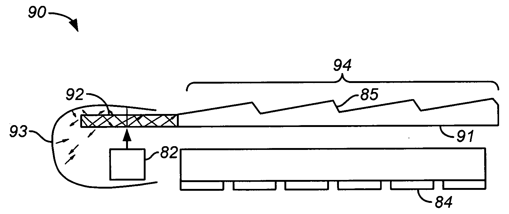
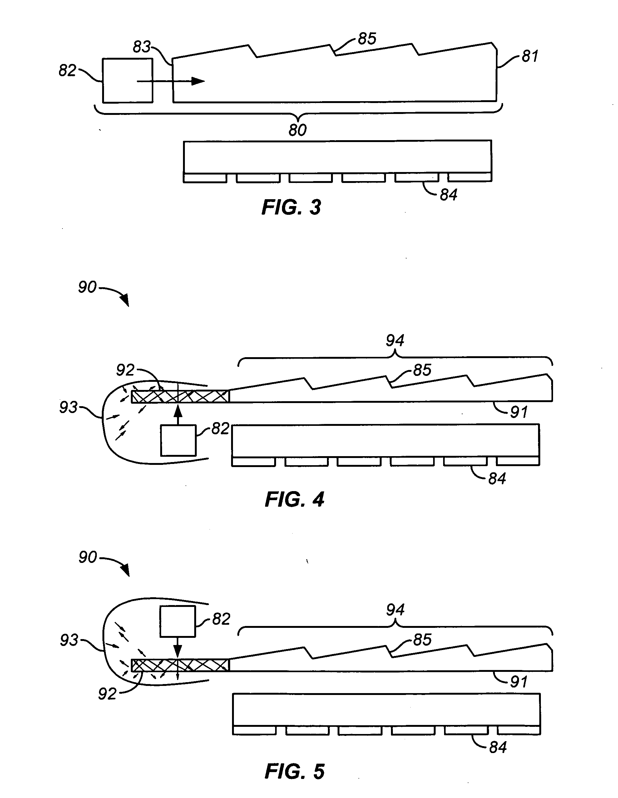
[0016]For example, the diffraction gratings in selected areas of the hologram may be formed to be less efficient at light extraction than the diffraction gratings in other areas of the hologram. The selected areas of the hologram may, for example, be proximate at least one light source. The selected areas may be selected to provide substantially uniform illumination of the display.

Problems solved by technology

However, illuminating the display uniformly and without creating artifacts has proven to be challenging.

Method used


Image

  • Dithered holographic frontlight
  • Dithered holographic frontlight
  • Dithered holographic frontlight

Examples


Embodiment Construction

[0034]While the present invention will be described with reference to a few specific embodiments, the description and specific embodiments are merely illustrative of the invention and are not to be construed as limiting the invention. Various modifications can be made to the described embodiments without departing from the true spirit and scope of the invention as defined by the appended claims. For example, the steps of methods shown and described herein are not necessarily performed in the order indicated. It should also be understood that the methods of the invention may include more or fewer steps than are indicated. In some implementations, steps described herein as separate steps may be combined. Conversely, what may be described herein as a single step may be implemented in multiple steps.

[0035]Similarly, device functionality may be apportioned by grouping or dividing tasks in any convenient fashion. For example, when steps are described herein as being performed by a single ...


PUM


Abstract

A reflective or transmissive hologram may be used to extract light from a waveguide. The hologram may be formed by separately exposing each of a plurality of areas of a holographic medium with object beams and / or reference beams having attributes (e.g., illumination angles) that vary randomly or pseudorandomly over the entire hologram. The areas may be contiguous (e.g., in a tiled pattern) or overlapping. In some embodiments, the spacing and / or orientation of the diffraction gratings may vary from area to area. For example, the spacing and / or orientation of the diffraction gratings may vary randomly or pseudorandomly from area to area. Some parts of the hologram may intentionally be made relatively more or relatively less efficient at extracting light from the waveguide.

Description

FIELD OF THE INVENTION[0001]This application relates generally to display technology and more specifically to the illumination of displays.BACKGROUND OF THE INVENTION[0002]There are various devices for display illumination. Some “frontlight” display illumination devices provide light to a waveguide and extract light out of the plane of the waveguide to illuminate a display that is substantially parallel to the waveguide. Various light-extracting elements may be used to extract the light out of the plane of the waveguide, such as prismatic films, holograms, etc. However, illuminating the display uniformly and without creating artifacts has proven to be challenging. Therefore, it would be desirable to provide improved frontlight illumination devices.SUMMARY[0003]Improved methods and devices are provided for display illumination. Some such devices use a reflective or transmissive hologram to extract light from a waveguide at angles that are nearly normal to the surface of the waveguide...

Claims


Application Information

Patent Timeline
Patent Type & Authority Applications(United States)
IPC IPC(8): G02B5/32G03H1/26G03H1/30F21V8/00
CPCG02B5/32G02B6/0035G02B6/0065G03H1/00G03H2001/0482G03H1/0408G03H1/26G03H2001/0439G03H1/04G02B6/00G03H1/22
Inventor SAMPSELL, JEFFREY BRIANMIENKO, MAREK
Owner SNAPTRACK
Learn More