Backlight module

a backlight module and module technology, applied in the field of backlight modules, can solve problems such as affecting the uniform brightness

Inactive Publication Date: 2010-09-23
ADVANCED OPTOELECTRONICS TECH
View PDF13 Cites 24 Cited by
  • Summary
  • Abstract
  • Description
  • Claims
  • Application Information

AI Technical Summary

Problems solved by technology

However, the LEDs are point light sources, and dark stripes would appear between two adjacent LEDs, due to a distance therebetween, thus affecting the uniform brightness.

Method used


Image

  • Backlight module
  • Backlight module
  • Backlight module

Examples


first embodiment

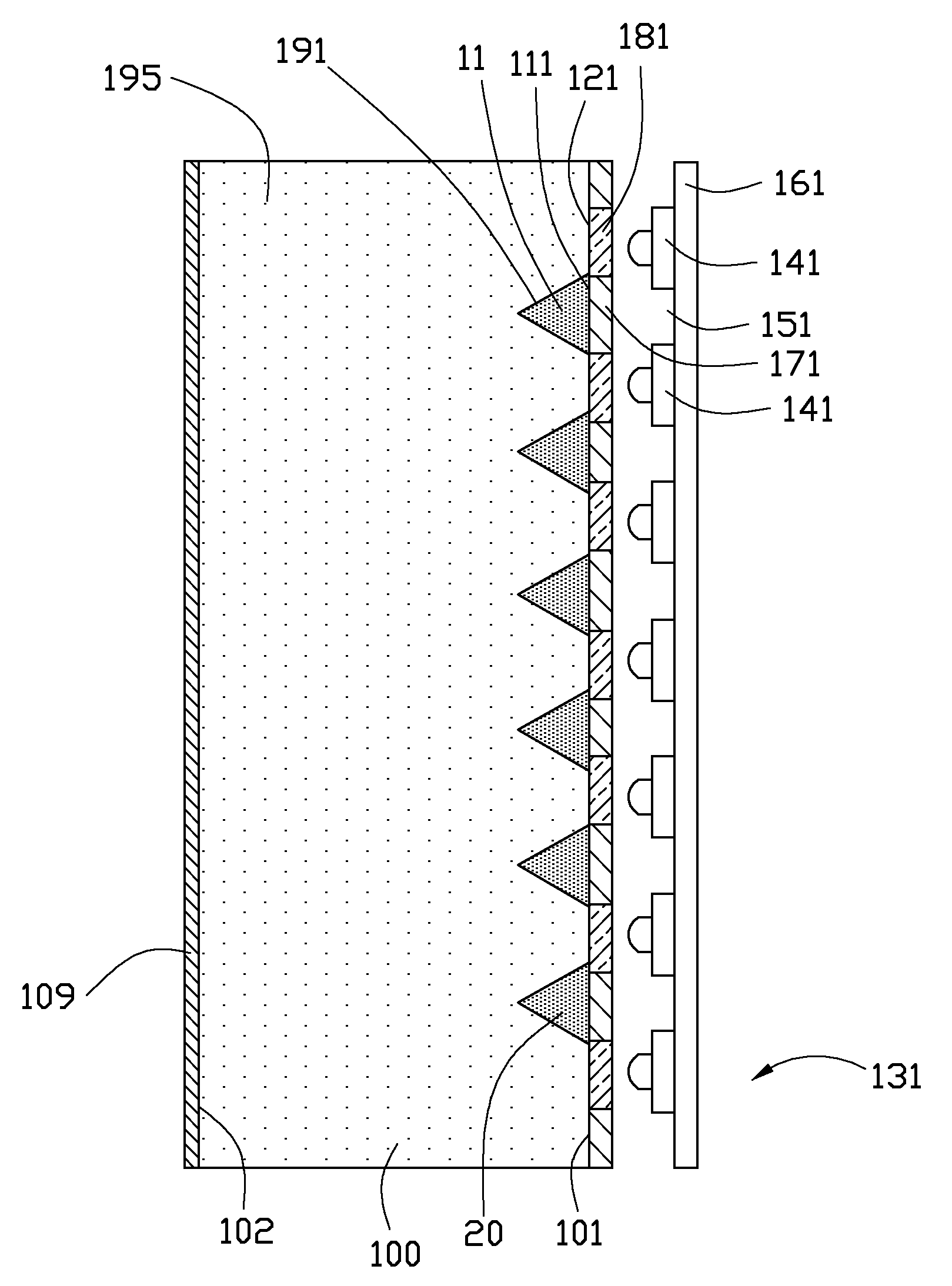
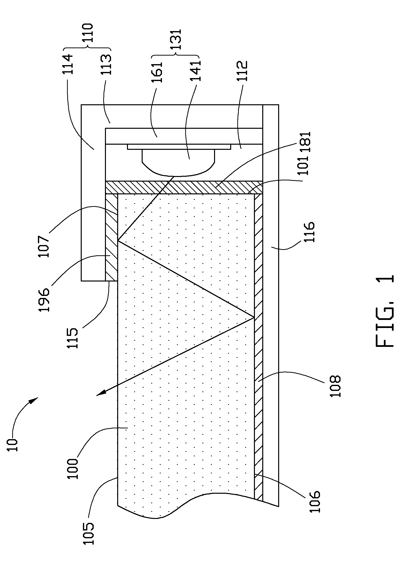
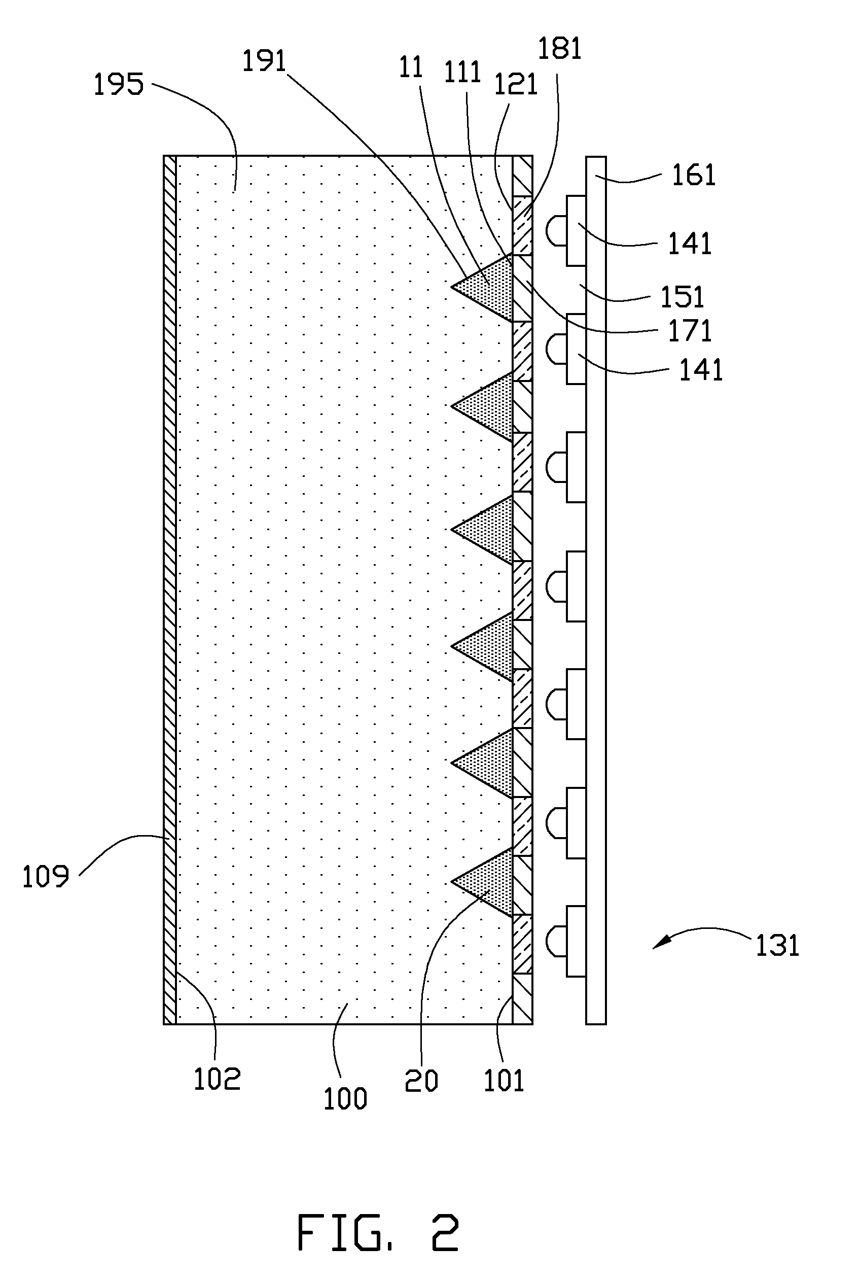
[0011]FIGS. 1-2 show a backlight module 10 in accordance with the present disclosure. The backlight module 10 includes a base plate 116, a frame 110, a light-emitting module 131 and a light guide plate 100. The base plate 116 is located on a bottom of the backlight module 10 and extends along a horizontal direction. The frame 110 is L-shaped in profile and includes a first plate 113 and a second plate 114. The first plate 113 extends perpendicularly from an end of the base plate 116. The second plate 114 is parallel to the base plate 116 and extends horizontally from a top of the first plate 113. The base plate 116 and the frame 110 cooperatively define a receiving chamber 112 having an opening 115 opposite to the first plate 113. The light-emitting module 131 is mounted on the first plate 113 and faces the opening 115 of the receiving chamber 112. One end of the light guide plate 100 is inserted into the receiving chamber 112 and disposed between the second plate 114 of the frame 1...

second embodiment

[0018]FIGS. 3-4 show a backlight module 20 according to a The backlight module 20 includes a first light-emitting module 231, a second light-emitting module 232 and a light guide plate 200. The light guide plate 200 includes a bottom surface 206, a light output surface 205, a first light incident surface 201 and a second light incident surface 202. The light output surface 205 is located at a top side of the light guide plate 200 and opposite to the bottom surface 206. The first light incident surface 201 is located at a right side of the light guide plate 200. The second light incident surface 202 is located at a left side of the light guide plate 200 and opposite to the first light incident surface 201. The first light incident surface 201 and the second light incident surface 202 interconnect with the light output surface 205 and the bottom surface 206. The first light incident surface 201 and the second light incident surface 202 are perpendicular and adjacent to the light outp...


PUM


Abstract

A backlight module includes a plurality of first light sources emitting first light and a light guide plate. The first light sources are arranged in a line and spaced from each other. Two adjacent first light sources define a first space therebetween. The light guide plate includes a first light incident surface and a light output surface. The first light incident surface has a plurality of bright areas respectively corresponding to the first light sources and a plurality of dark areas respectively corresponding to the first spaces. A plurality of first reflectors is disposed on the plurality of dark areas of the first incident surface. The light output surface is adjacent and perpendicular to the light incident surface.

Description

BACKGROUND[0001]1. Technical Field[0002]The present disclosure relates to a backlight module. More particularly, the present disclosure relates to a light-emitting diodes (LED) backlight module that can reduce dark stripes (or hot spot mura).[0003]2. Description of Related Art[0004]A backlight module is a fundamental part in a liquid crystal display (LCD). Since liquid crystal does not emit light itself, the backlight module is needed for providing the required light source. The principle for operating a backlight module is to direct the light emitted from a backlight source as a planar light source via a light guide plate, thereby assuring uniform brightness. LEDs are extensively used as a backlight source in the backlight module in virtue of high brightness, low work voltage, low power consumption, a long lifetime and so on. However, the LEDs are point light sources, and dark stripes would appear between two adjacent LEDs, due to a distance therebetween, thus affecting the uniform...

Claims


Application Information

Patent Timeline
Patent Type & Authority Applications(United States)
IPC IPC(8): F21V7/04
CPCG02B6/0025G02B6/0061G02B6/0031
Inventor CHIU, KUAN-HERCHEN, IRENE
Owner ADVANCED OPTOELECTRONICS TECH
Why Eureka
Try Eureka