Power supply apparatus
- Summary
- Abstract
- Description
- Claims
- Application Information
AI Technical Summary
Benefits of technology
Problems solved by technology
Method used
Image
Examples
first embodiment
[0059]Next, the first embodiment that has a configuration based on the above-described configuration will be described.
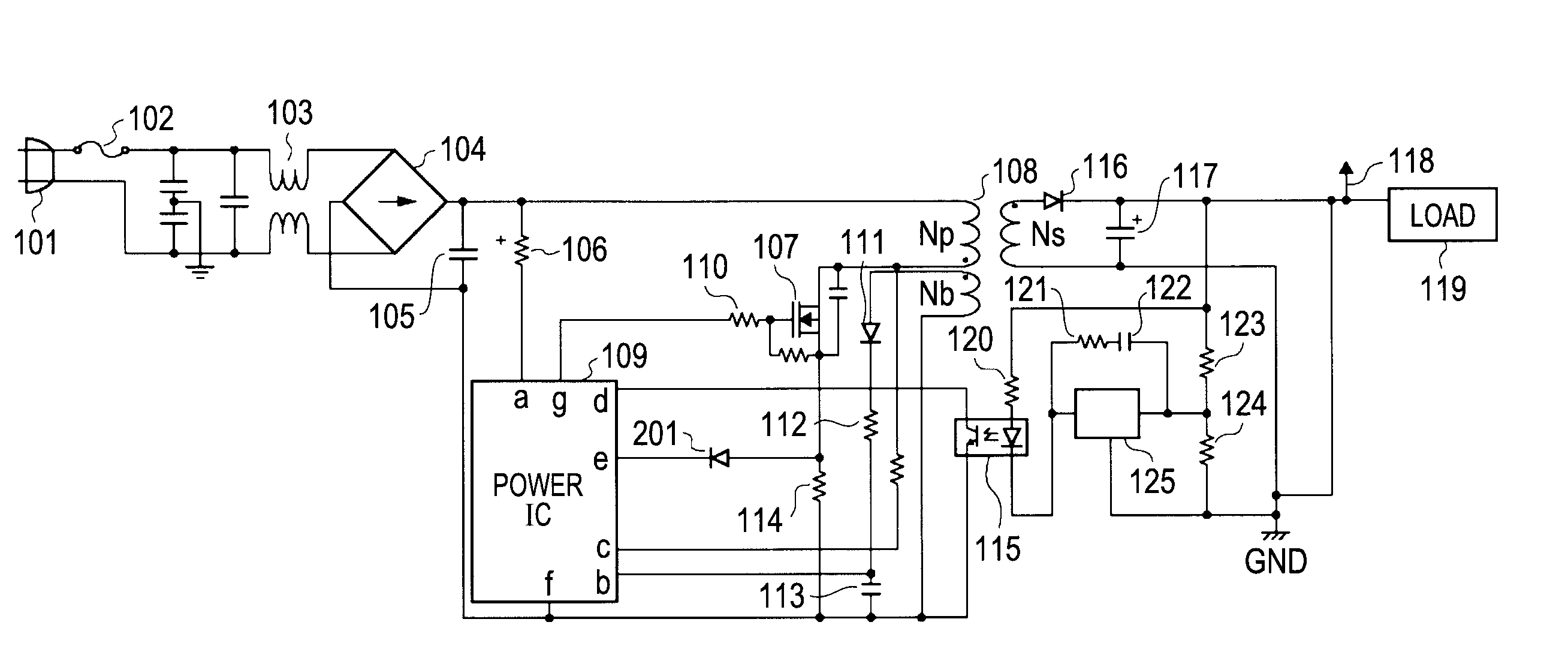
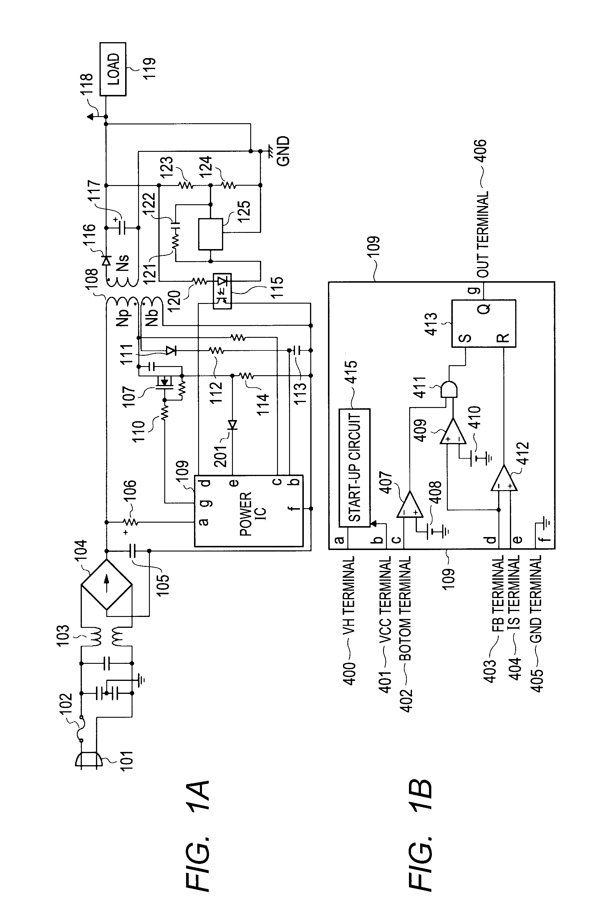
[0060]FIGS. 1A and 1B illustrate an example of the circuit configuration of the DC power supply apparatus according to the first embodiment. Specifically, FIG. 1A illustrates the entire configuration of the DC power supply apparatus and FIG. 1B illustrates a configuration example of the power control IC 109. Since the configuration of the power control IC 109 is the same as that of FIG. 12B illustrated in the related art, the detailed description thereof will be omitted. The description of the same configuration as that of FIG. 12A will be omitted and only a feature portion of the first embodiment will be described.
[0061]
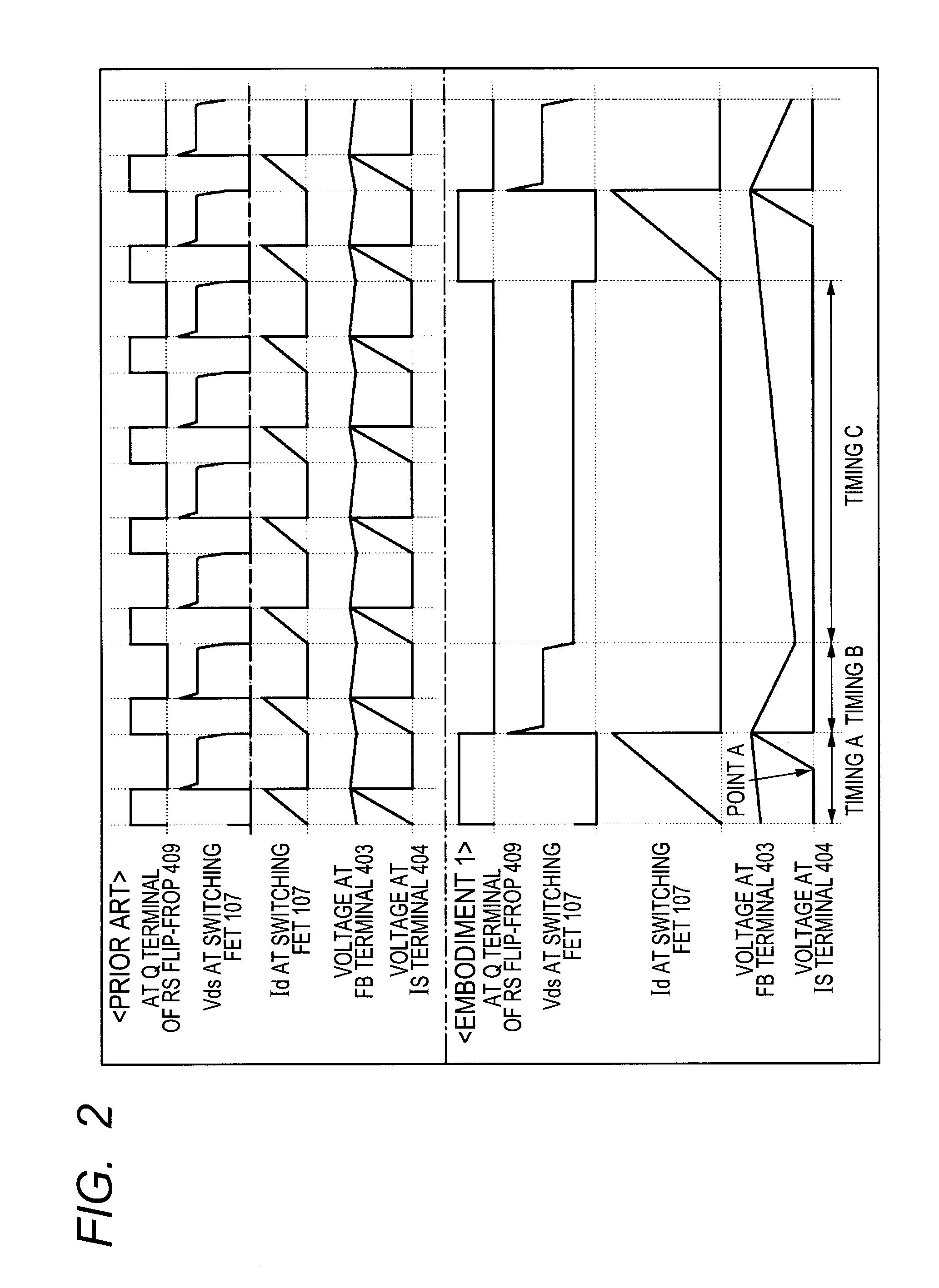
[0062]In the first embodiment, the diode 201 is connected between the IS terminal 404(e) of the power control IC 109 and a current inflow end of the current detection resistor 114 that is a voltage detection point for current detection of the primar...
second embodiment
[0067]In the case of the related art, P1=½×L×I12 where P1: energy that is accumulated in the transformer 108, L: an L value (common to the related art and the second embodiment) of the transformer 108, and I1: Id peak of the switching FET 107).
[0068]In the case of the first embodiment, P2=½×L×I22 where P2: energy that is accumulated in the transformer 108, L: an L value (common to the related art and the second embodiment) of the transformer 108, and I2: Id peak of the switching FET 107).
[0069]Accordingly, if the switching frequency is reduced to ⅙, I2=(6×I1)1 / 2 is obtained from 6×P1=P2. That is, the conductive time of the switching FET 107 in the first embodiment increases by 61 / 2 times as compared with the related art. If the peak current of the IS terminal 404 is defined as VIS, Vf=(61 / 2−1)×VIS is obtained from 1+Vf / VIS=61 / 2.
[0070](Timing B of FIG. 2) The timing B indicates a period of time when the energy accumulated in the transformer 108 as a flyback current flows into the sec...
PUM
 Abstract
Description
Claims
Application Information
 - R&D
- Intellectual Property
- Life Sciences
- Materials
- Tech Scout
- Unparalleled Data Quality
- Higher Quality Content
- 60% Fewer Hallucinations
Browse by: Latest US Patents, China's latest patents, Technical Efficacy Thesaurus, Application Domain, Technology Topic, Popular Technical Reports.
© 2025 PatSnap. All rights reserved.Legal|Privacy policy|Modern Slavery Act Transparency Statement|Sitemap|About US| Contact US: help@patsnap.com


