
Organic Electroluminescent Device

Active Publication Date: 2014-02-27
UDC IRELAND
View PDF3 Cites 2 Cited by
  • Summary
  • Abstract
  • Description
  • Claims
  • Application Information

AI Technical Summary

Benefits of technology

The present invention is about an organic electroluminescent device that can efficiently extract light from the organic materials used in it, while also consuming less power and having a longer lifespan. This solves the problems that were previously present in this technology.

Problems solved by technology

Therefore, when light is emitted at an angle equal to or higher than a critical angle determined based on the refractive index of the organic electroluminescent layer and the refractive index of a medium into which the light is to be emitted, the light cannot be emitted to the air, totally reflected, and confined in the interior of the organic electroluminescent layer, so that the light is lost.
Extraction of the back-scattered components depends on the reflectivity of a reflective electrode, and the reflective electrode of MgAg is inferior to a reflective electrode of Ag in terms of reflectivity, which is problematic.
In addition, since the light emitted from the organic electroluminescent layer travels at all angles, when the light travels in the thickness direction and reflected, scattered and totally reflected, the light hits the wall surfaces of the organic electroluminescent layer and is lost, which is also problematic.
Thus, this proposal is unsatisfactory for making improvement in light extraction efficiency.
This proposal, however, does not clearly describe the refractive index of the polymer in the fine particle layer, and when it is lower than the refractive index of the organic electroluminescent layer, total reflection occurs so that the light emitted from the organic electroluminescent layer cannot enter the fine particle layer.
Thus, this proposal is unsatisfactory for making improvement in light extraction efficiency.

Method used


Image

  • Organic Electroluminescent Device
  • Organic Electroluminescent Device
  • Organic Electroluminescent Device

Examples


example 1

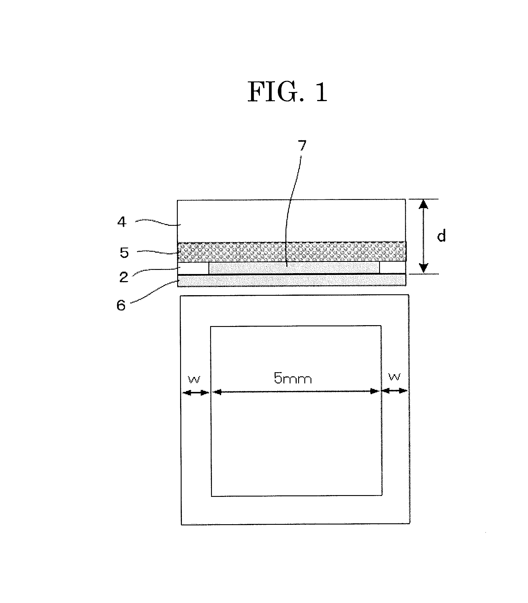
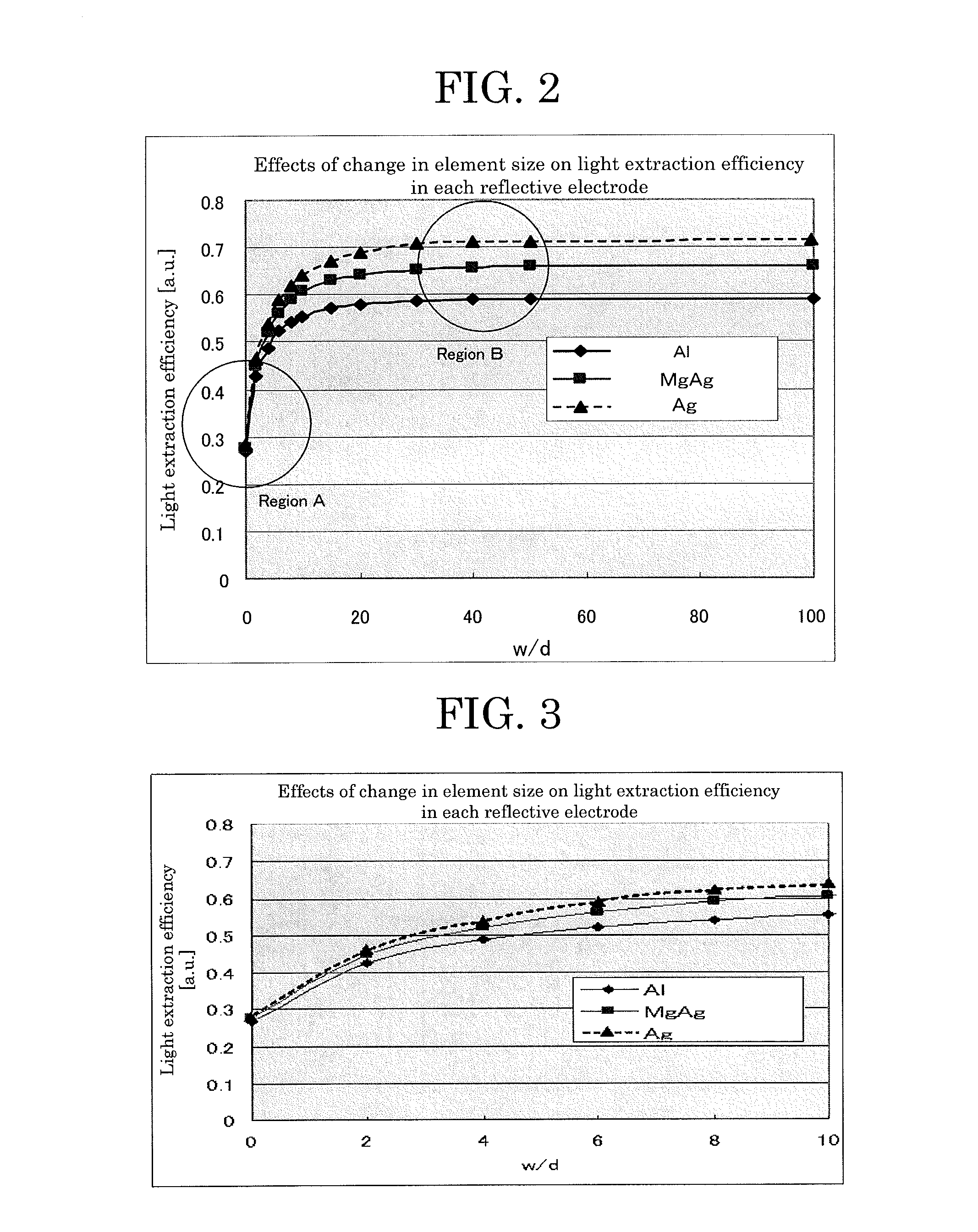
[0249]—In each reflective electrode, effects on the light extraction efficiency when the size of the effective light-emitting region is changed with respect to the thickness of the element—

>

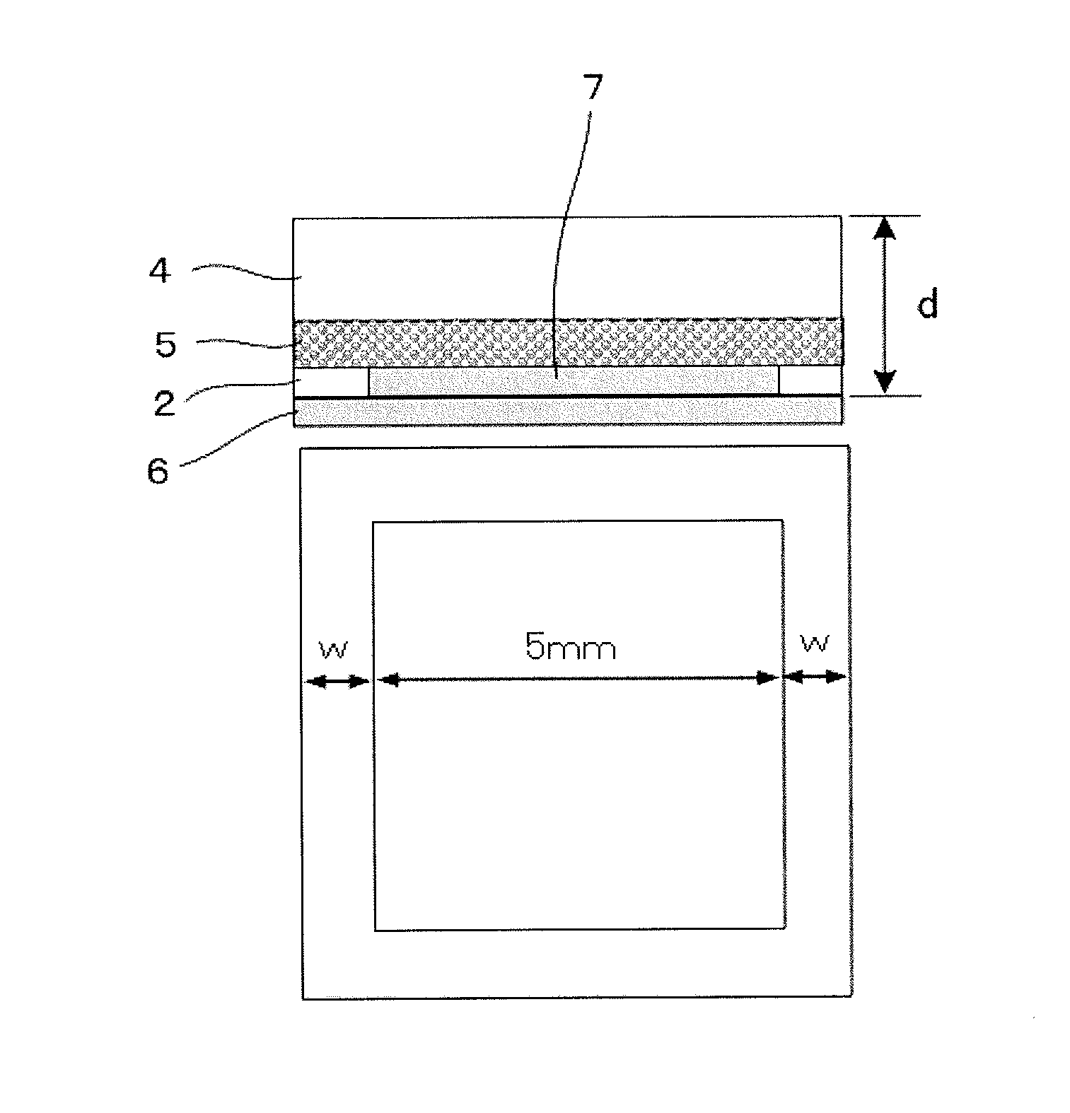
[0250]As depicted in FIG. 1, a specific configuration of the simulation model is as follows:

air / transparent substrate 4 (refractive index ns=1.5, attenuation coefficient k=0, thickness: 1 mm) / fine particle layer 5 (polystyrene fine particles: average particle diameter φ=2 μm, refractive index np=1.59, attenuation coefficient k=0, filling rate by volume n=50%; polymer: refractive index nb=1.8, attenuation coefficient k=0, thickness=15 μm) / organic electroluminescent layer 2 (refractive index n=1.8, attenuation coefficient k=0, thickness: 0.2 μm) / composite reflective layer 6 (Ag: reflectivity 0.87, MgAg: reflectivity 0.83, Al: reflectivity 0.77, thickness: 100 nm).

[0251]Using commercially available ray-tracing software (ZEMAX-EE, product of ZEMAX Development Corporation), simulation was performed ab...

example 2

[0257]—In each reflective electrode, optimization of the fine particle layer in terms of the refractive index of the polymer, the average particle diameter of the fine particles, and the filling rate by volume of the fine particles—

>

[0258]Using commercially available ray-tracing software (ZEMAX-EE, product of ZEMAX Development Corporation), simulation was performed about the effects on the light extraction efficiency by changing the parameters of the fine particle layer. Here, based on the point at which the light extraction efficiency in the case of the Ag reflective electrode, the MgAg reflective electrode or the Al reflective electrode stopped increasing in FIG. 2 of Simulation 1, the effective light-emitting region is a mm×5 mm square and the entire element is a 40 mm×40 mm square.

(1) Model where the Fine Particle Layer is Absent (See FIG. 5)

[0259]Air / transparent substrate 4 (BK7, product of OHARA INC., refractive index n=1.5, attenuation coefficient k=0, thickness=1 mm) / organic...


PUM


Abstract

Provided is an organic electroluminescent device including, in an order mentioned: a reflective electrode; an organic electroluminescent layer; a light extraction layer; and a transparent substrate, wherein a ratio (w / d) is 9 or more where “d” denotes a total average thickness from the organic electroluminescent layer to the transparent substrate and “w” denotes a minimum width of a non-light-emitting region present outside of an outer periphery of an effective light-emitting region in the organic electroluminescent layer.

Description

TECHNICAL FIELD[0001]The present invention relates to an organic electroluminescent device (hereinafter may be referred to as “organic EL device” and “organic electroluminescence device”).BACKGROUND ART[0002]Organic electroluminescent devices are self-emission type display devices and are expected for use in displays and lights. Organic electroluminescent displays have advantageous display performances such as higher visibility than conventional CRTs and LCDs, and no viewing angle dependency. Organic electroluminescent displays also have an advantage that they can be made lighter and thinner. Meanwhile, organic electroluminescent lights can be advantageously lighter and thinner and also, using a flexible substrate, organic electroluminescent lights may have a shape conventional lights cannot have.[0003]An organic electroluminescent layer of an organic electroluminescent device has a multi-layered structure containing a light-emitting layer, a transparent electrode and other layers. ...

Claims


Application Information

Patent Timeline
IPC IPC(8): H01L51/52
CPCH01L51/5268H10K50/826H10K50/85H10K50/854H10K2102/351H10K50/82
Inventor LI, JINGBOSONODA, SHINICHIRO
Owner UDC IRELAND
Learn More