

A/D converter circuit and current supply circuit
- Summary
- Abstract
- Description
- Claims
- Application Information
AI Technical Summary
Benefits of technology
Problems solved by technology
Method used
Image

Examples
first embodiment
[0107] (First Embodiment)
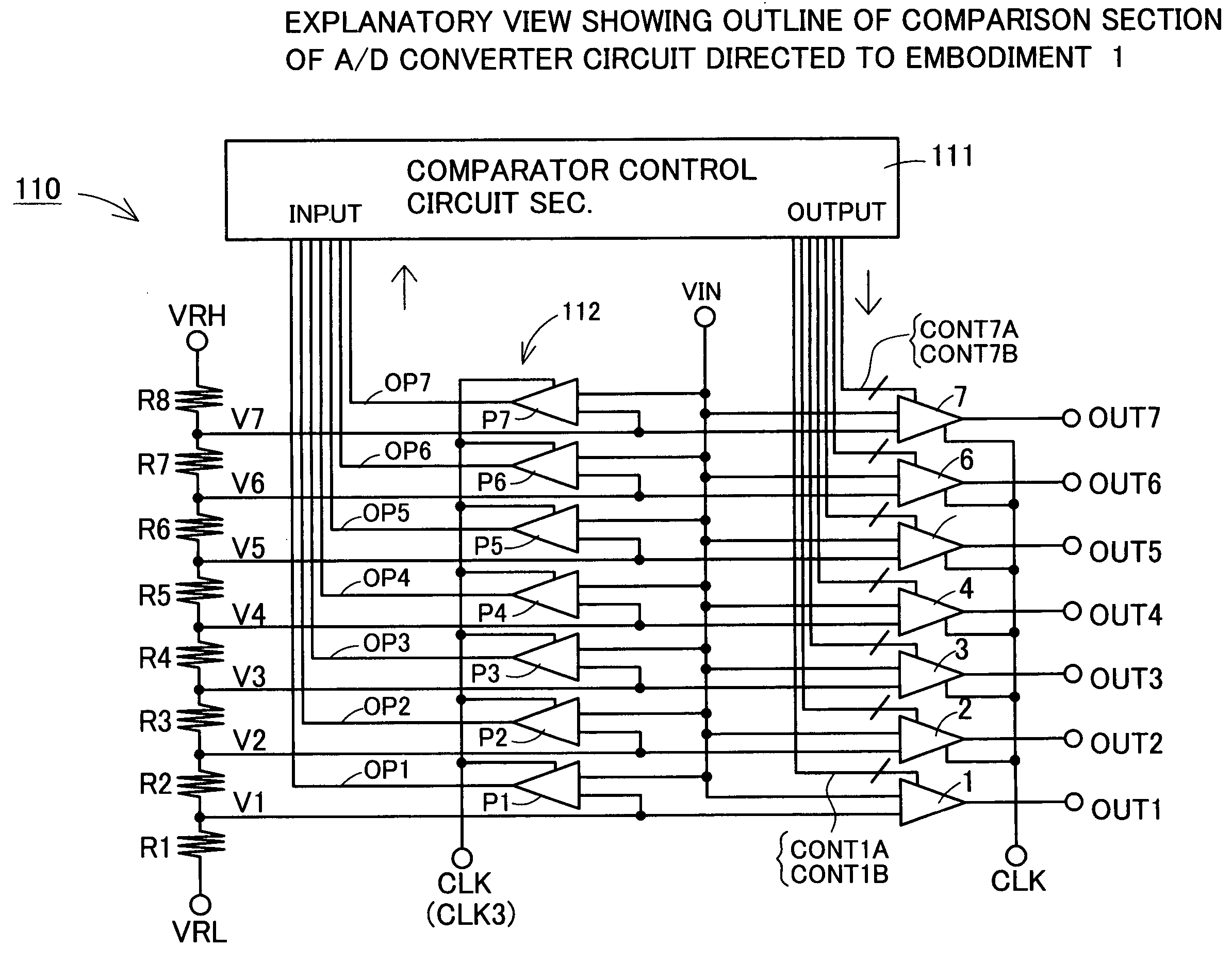
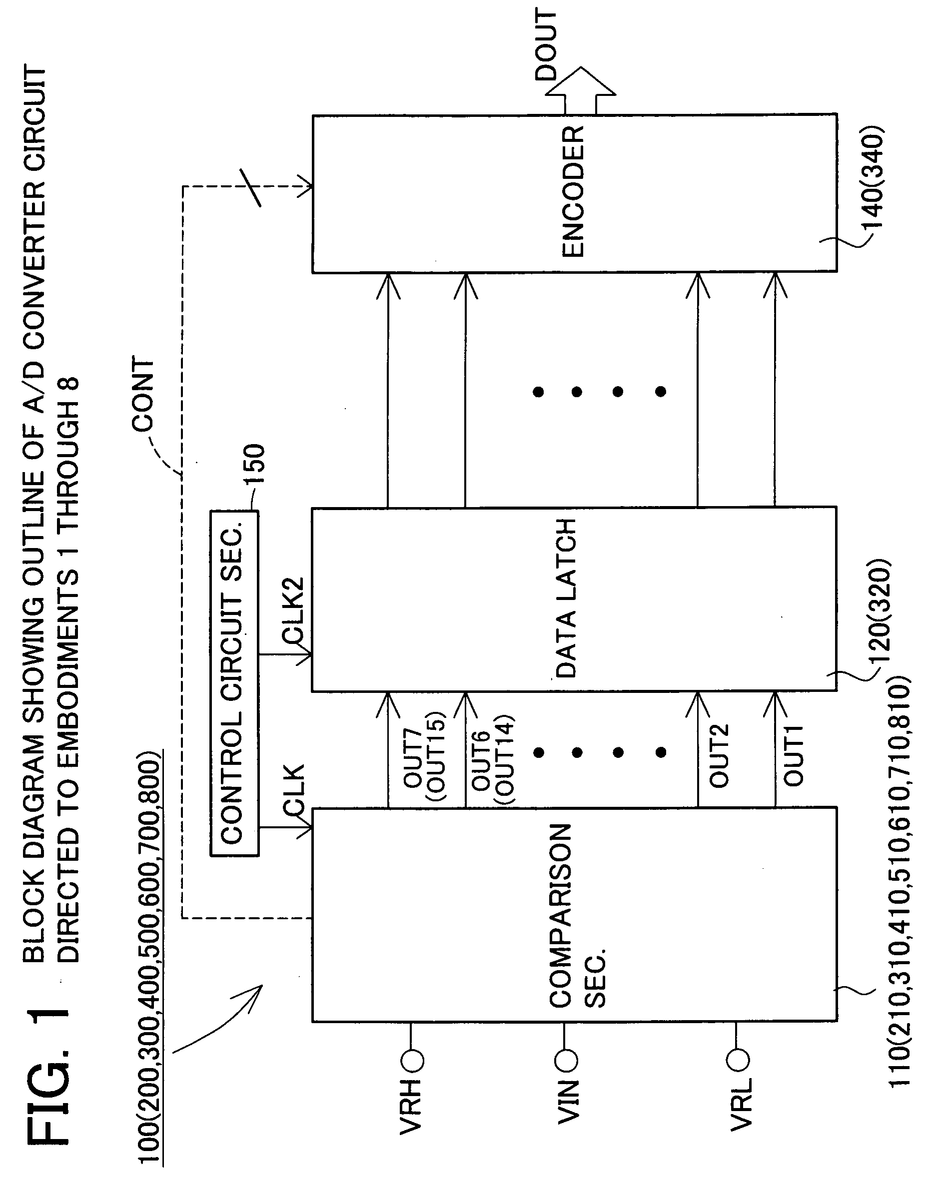
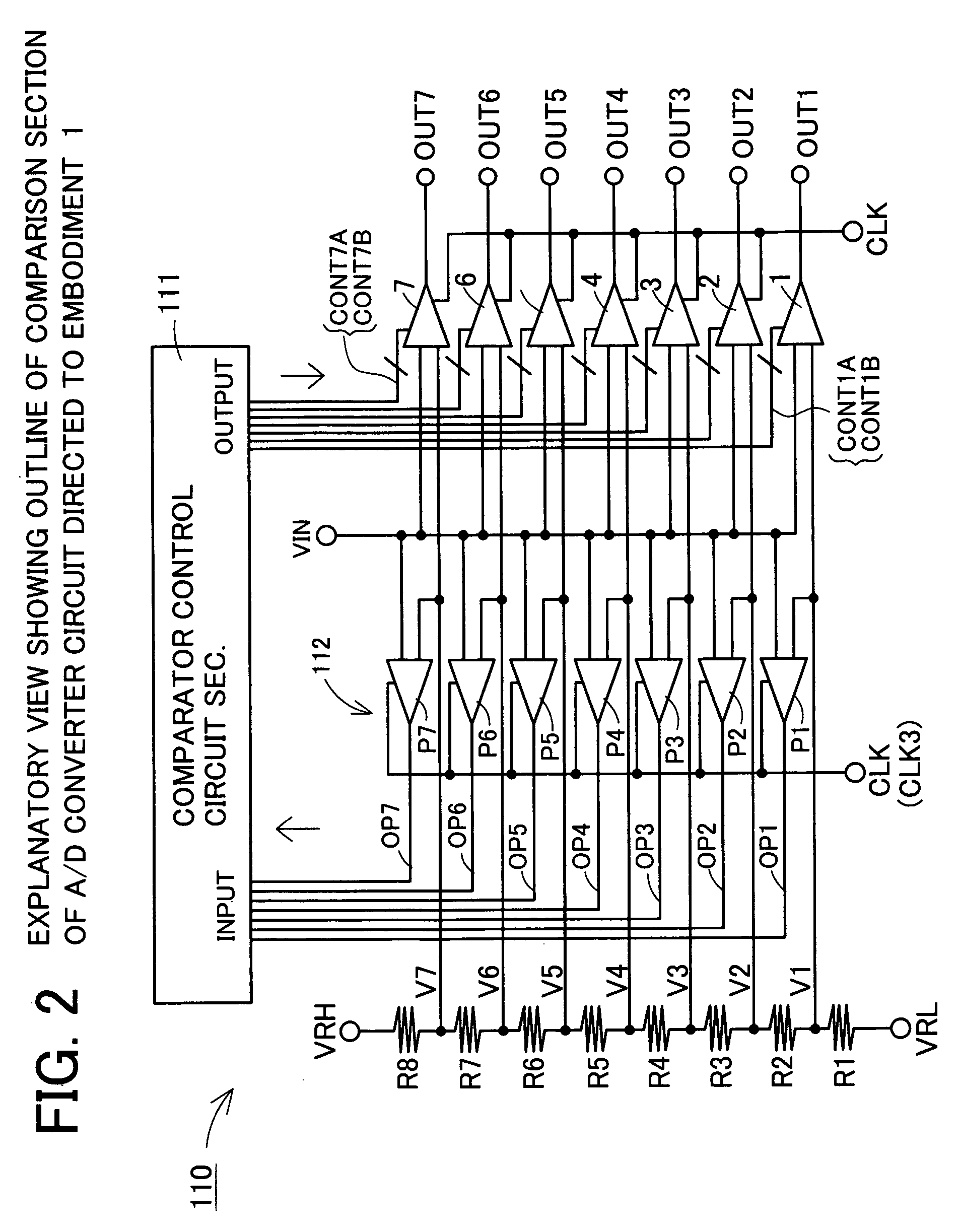
[0108] A parallel-type A / D converter circuit 100 directed to a first embodiment of this invention will be described with reference to FIG. 1-FIG. 10. Of these, FIG. 1 is a block diagram showing the outline of the A / D converter circuit, FIG. 2 is an explanatory view showing the outline of a comparison section of this, FIG. 3 is a table showing a relationship between input voltage, outputs of conversion comparators, and output codes. And, FIG. 4 is a table showing a relationship between input voltage a predetermined time past, outputs of setting comparators, and set states of conversion comparators. FIG. 5 is an explanatory view showing the construction of a main part of a chopper-type conversion comparator, FIG. 6 is a table showing a relationship of the operation of this part and its switches, FIG. 7 is a circuit diagram showing the circuit construction of an inverter device, and FIG. 8 is a graph showing a relationship between the input voltage and drain cu...
second embodiment
[0159] (Second Embodiment)
[0160] Next, a parallel-type A / D converter circuit 200 directed to a second embodiment will be described, with reference to FIG. 12-FIG. 14. The A / D converter circuit 200 of this Embodiment 2 is a 3-bit A / D converter circuit, like the A / D converter circuit 100 of Embodiment 1. However, as can be understood by comparing FIG. 12 and FIG. 2, it differs in the point that in a comparison section 210, it has no setting comparators P1-P7. Accordingly, the explanation will center on the different parts, and similar parts have been given the same numbers and their explanation will be omitted or simplified.
[0161] The A / D converter circuit 200 also is a circuit for converting an analog voltage VIN to a 3-bit digital output DOUT at intervals of a predetermined period applied with a clock signal CLK, and has the comparing section 210, a data latch 120, an encoder 140 and a control circuit section 150 (see FIG. 1). To the comparing section 210 is inputted, besides a hig...
third embodiment
[0193] (Third Embodiment)
[0194] Next, a parallel-type A / D converter circuit 300 directed to a third embodiment will be described, with reference to FIG. 16-FIG. 19. The A / D converter circuit 300 of this Embodiment 3 is the same as Embodiment 2 in that it does not use setting comparators, but differs in the point that it is a 4-bit A / D converter circuit and uses 15 comparators 1-15, and in the point that it performs state-setting of the comparators with the first and second setting signals CONTG1A etc. group by group, with two comparators as one group, as in comparators 2 and 3, 4 and 5, and so on. Accordingly, the explanation will center on the different parts, and similar parts have been given the same numbers and their explanation will be omitted or simplified.
[0195] The A / D converter circuit 300 also is a circuit for converting an analog voltage VIN to a digital output DOUT at intervals of a predetermined period applied with a clock signal CLK, and has a comparing section 310, a...
PUM
 Abstract
Description
Claims
Application Information