Device for Determining the 3D Coordinates of an Object, In Particular of a Tooth

a 3d coordinate and object technology, applied in the field of scanning scanners, can solve the problem of difficult access to objects to be scanned

Active Publication Date: 2010-09-23
CARL ZEISS OPTOTECHN GMBH
View PDF22 Cites 45 Cited by
  • Summary
  • Abstract
  • Description
  • Claims
  • Application Information

AI Technical Summary

Benefits of technology

[0006]The scanner comprises a carrier on which a plurality of projectors for projecting a pattern onto the object and a plurality of cameras for recording the object are provided in an array. The projectors can be arranged as an array. The arrangement of the projectors and carriers in accordance with the invention is suitable in particular for use under cramped space conditions and in hard-to-reach areas, as they exist for instance in the oral cavity of a patient, in which the teeth should be scanned. The multitude of cameras ensures that a sufficient number of different images can be made for evaluation. The multitude of projectors ensures that a sufficient number of patterns can be projected onto the regions of the teeth to be scanned.

Problems solved by technology

However, it is also particularly useful for other applications in which the objects to be scanned are hard to reach.

Method used


Image

  • Device for Determining the 3D Coordinates of an Object, In Particular of a Tooth
  • Device for Determining the 3D Coordinates of an Object, In Particular of a Tooth
  • Device for Determining the 3D Coordinates of an Object, In Particular of a Tooth

Examples


Embodiment Construction

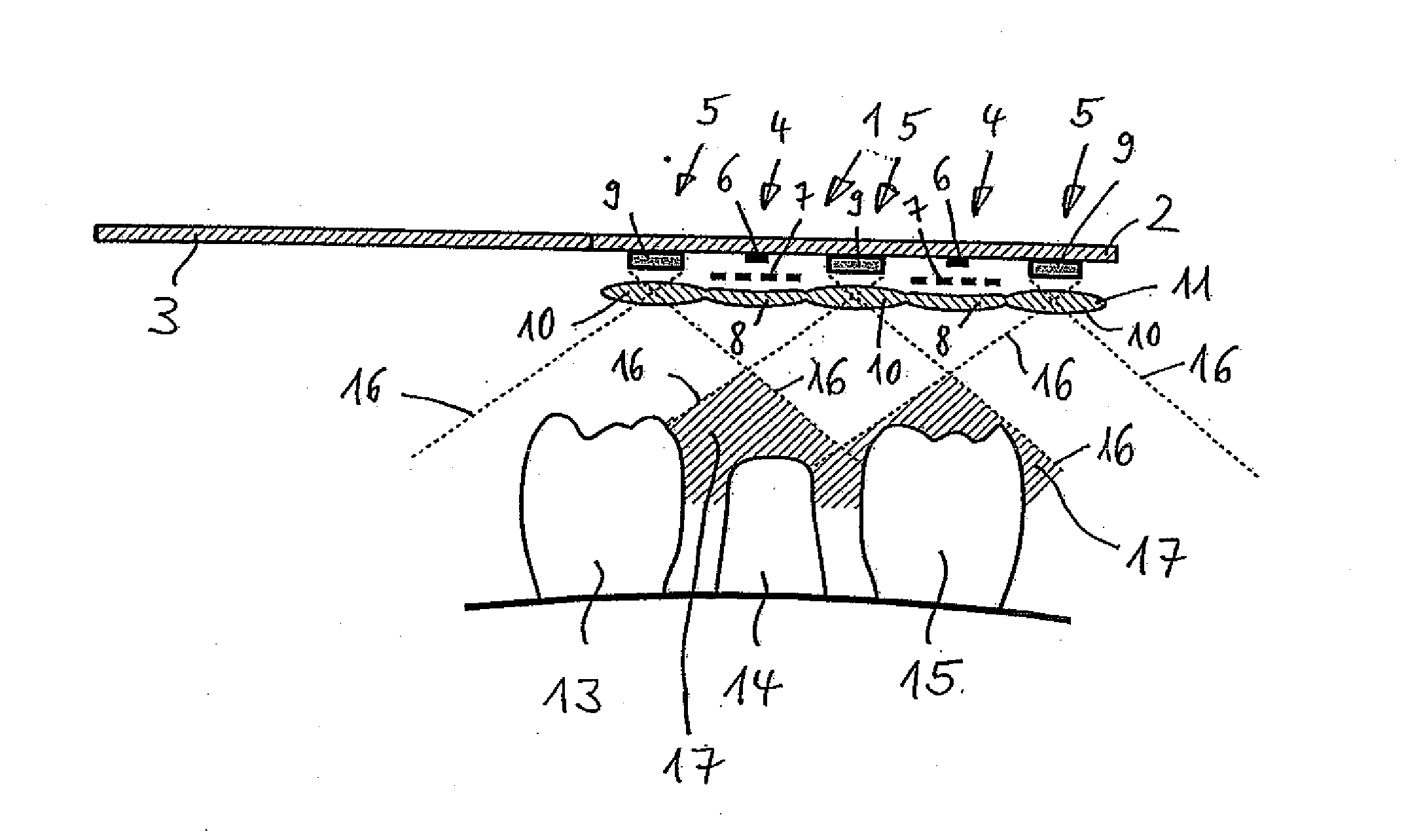
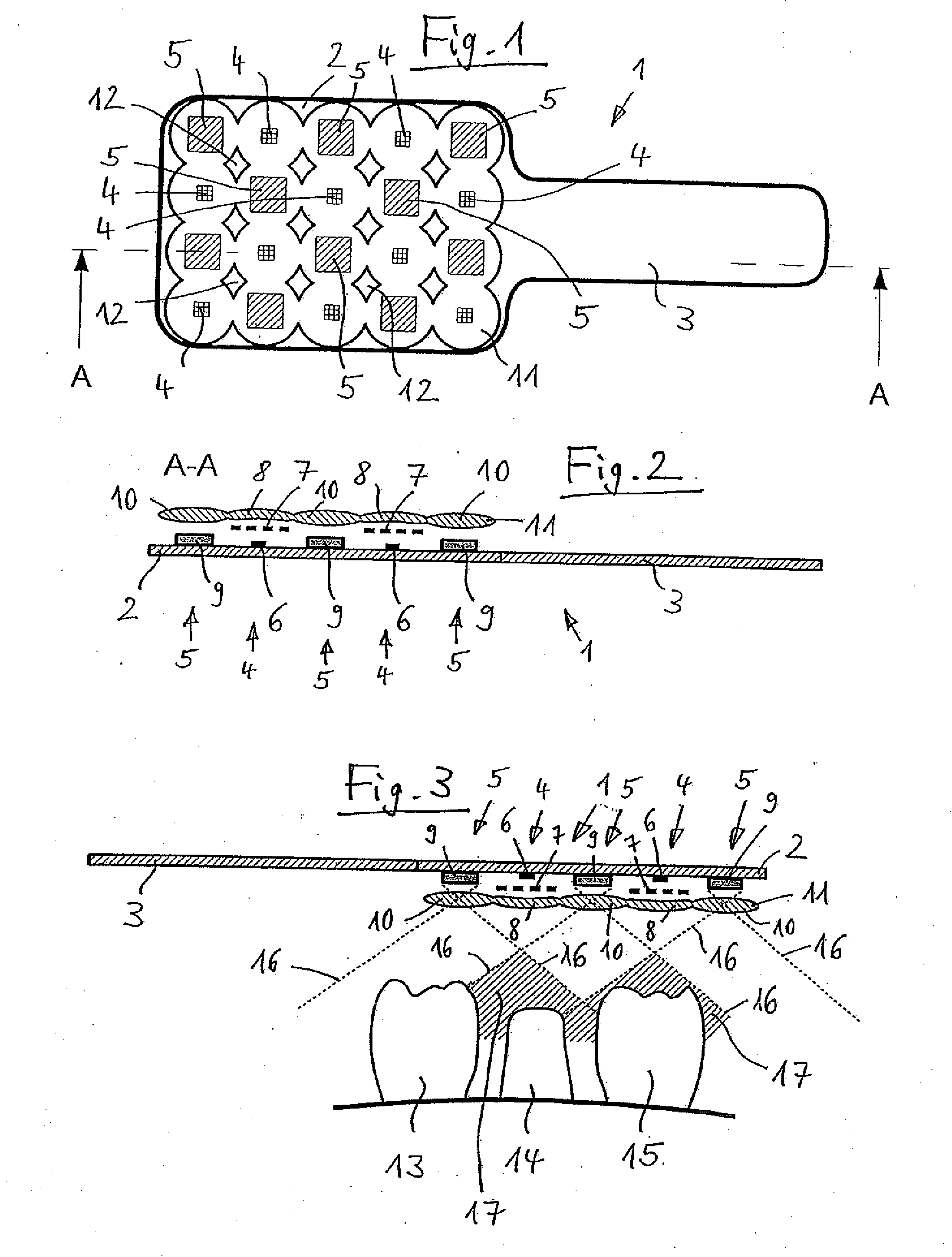
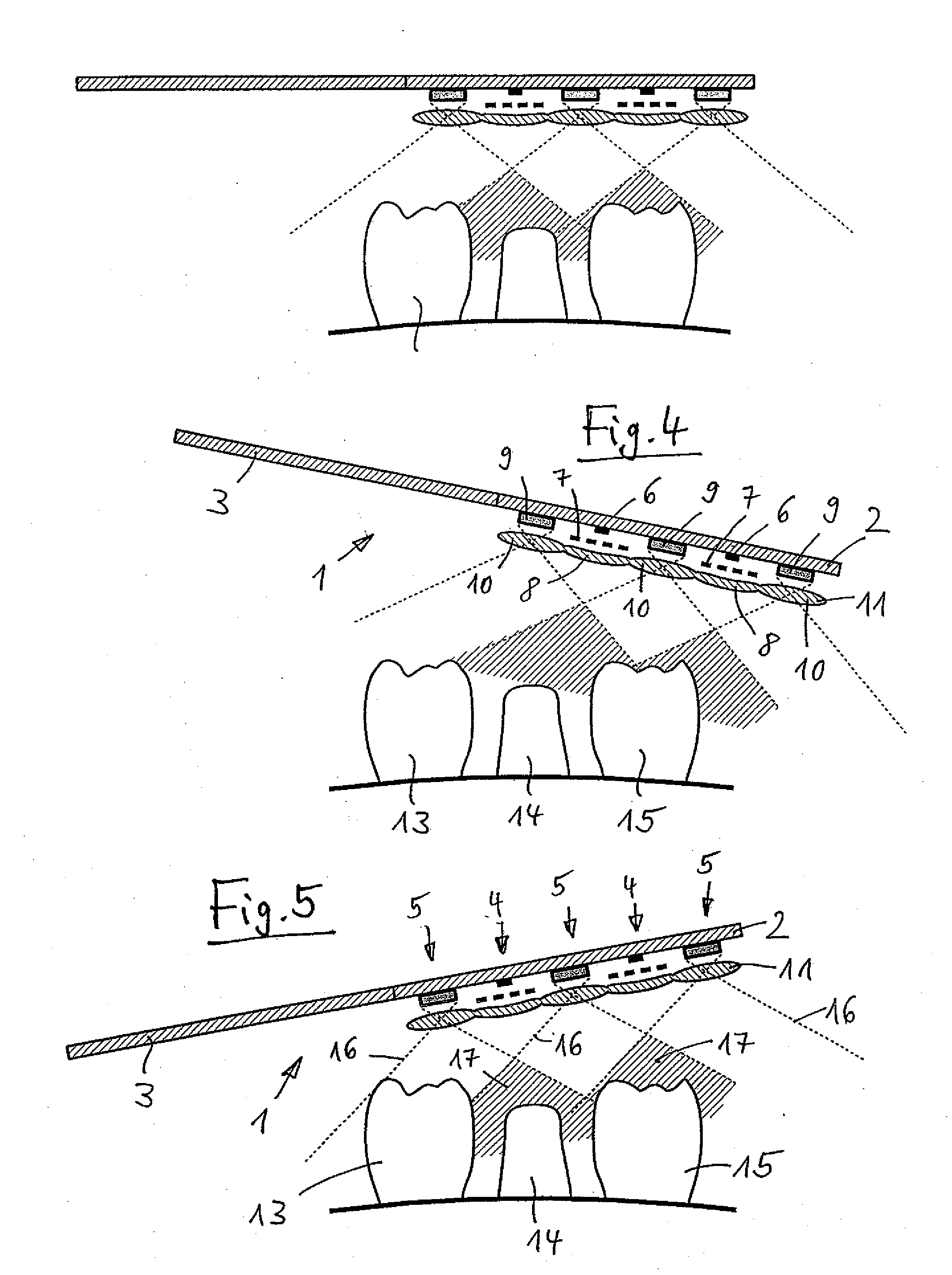
[0032]FIGS. 1 to 5 show a scanner 1 which comprises a flat carrier 2 and a handle part 3. On the carrier 2, ten projectors 4 and ten cameras 5 are provided one beside the other in a two-dimensional arrangement (“array”). The projectors 5 and the cameras 5 are alternately arranged on the carrier 2. In the uppermost row, from the left to the right, a camera 5, a projector 4, a camera 5, a projector 4 and a camera 5 are disposed. In the second row, from the left to the right, a projector 4, a camera 5, a projector 4, a camera 5 and a projector 4 are disposed. The third and fourth rows are configured like the first and second rows. In both directions, the projectors 4 and the cameras 5 alternate in a ratio of 1:1.

[0033]FIG. 2 shows that each projector 4 comprises a light source 6, a mask 7 and a projector optics 8. The light source 6 is formed by an LED. The mask 7 is formed by a slide or LCD. The projector optics 8 consists of a lens.

[0034]Each camera 5 comprises an image sensor 9 and ...


PUM


Abstract

A scanner is used for scanning an object, in particular one or more teeth (13, 14, 15) or a dental cast. An improved scanner comprises a carrier (2) on which a plurality of projectors (4) for projecting a pattern onto the object and a plurality of cameras (5) for recording the object are provided one beside the other in an array.

Description

BACKGROUND OF THE INVENTION[0001]This invention relates to a scanner for scanning an object, in particular one or more teeth or a dental cast, and a device for determining the 3D coordinates of an object, in particular of one or more teeth or a dental cast. Teeth in the sense of the invention are understood to be prepared teeth and also dental prostheses.[0002]Devices and methods for determining the 3D coordinates of an object are already known. EP 299 490 B2 describes a method for producing a dental prosthesis, in which isoheight or contour lines are generated on the ground-down tooth and its surroundings, the lines are detected with an optoelectronic means, in particular a video camera, the values detected are entered in a computer, and the spatial structure of the tooth and the dental prosthesis is calculated. With reference to the structure thus calculated, the dental prosthesis can be fabricated.[0003]From the non-prepublished German Patent Application 10 2007 060 263.6 with th...

Claims


Application Information

Patent Timeline
Patent Type & Authority Applications(United States)
IPC IPC(8): G06K9/00
CPCG01B11/03A61C9/0053G01B11/2513G01B11/245A61C9/006G01C11/02
Inventor GANDYRA, MICHAELSTEINBICHLER, MARCUS
Owner CARL ZEISS OPTOTECHN GMBH
Why Eureka
Try Eureka