Accelerated Data Structure Optimization Based Upon View Orientation

a data structure and view orientation technology, applied in image data processing, instruments, computer peripheral equipment, etc., can solve the problems of low amount of computational power, rasterization suffers from several drawbacks, and modern monitors display images, so as to reduce processing resources, reduce the impact of resulting image frames, and optimize the generation and/or use

Inactive Publication Date: 2010-09-23
IBM CORP
View PDF3 Cites 38 Cited by
  • Summary
  • Abstract
  • Description
  • Claims
  • Application Information

AI Technical Summary

Benefits of technology

[0023]The invention addresses these and other problems associated with the prior art by providing a circuit arrangement, program product and method that utilize the known view orientation for an image frame to be rendered to optimize the generation and/or use of an Accelerated Data Structure (ADS) used in physical rendering-based image processing. In particular, it has been found that while geometry primitives that are not within a view orien...

Problems solved by technology

One limitation of rendering realistic images is that modern monitors display images through the use of pixels.
Rasterization is effective at rendering graphics quickly and using relatively low amounts of computational power; however, rasterization suffers from several drawbacks.
For example, rasterization often suffers from a lack of realism because it is not based on the physical properties of light, rather rasterization is based on the shape of three-dimensional geometric objects in a scene projected onto a two dimensional plane.
Furthermore, the computational power required to render a scene with rasterization scales directly with an increase in the complexity of the scene to be rendered.
As image processing becomes more realistic, rendered scenes also become more complex.
Therefore, rasterization suffers as image processing evolves, because rasterization scales directly with complexity.
Furthermore, ray tracing also handles increases in scene complexity better than rasterization as scenes become more complex.
This is due to the fact that the same number of rays may be cast into a scene, even if the scene becomes more complex.
One major drawback of ray tracing, however, is the large number of calculations, and thus processing power, required to render scenes.
This leads to problems when fast rendering is needed, e.g...

Method used


Image

  • Accelerated Data Structure Optimization Based Upon View Orientation
  • Accelerated Data Structure Optimization Based Upon View Orientation
  • Accelerated Data Structure Optimization Based Upon View Orientation

Examples


Embodiment Construction

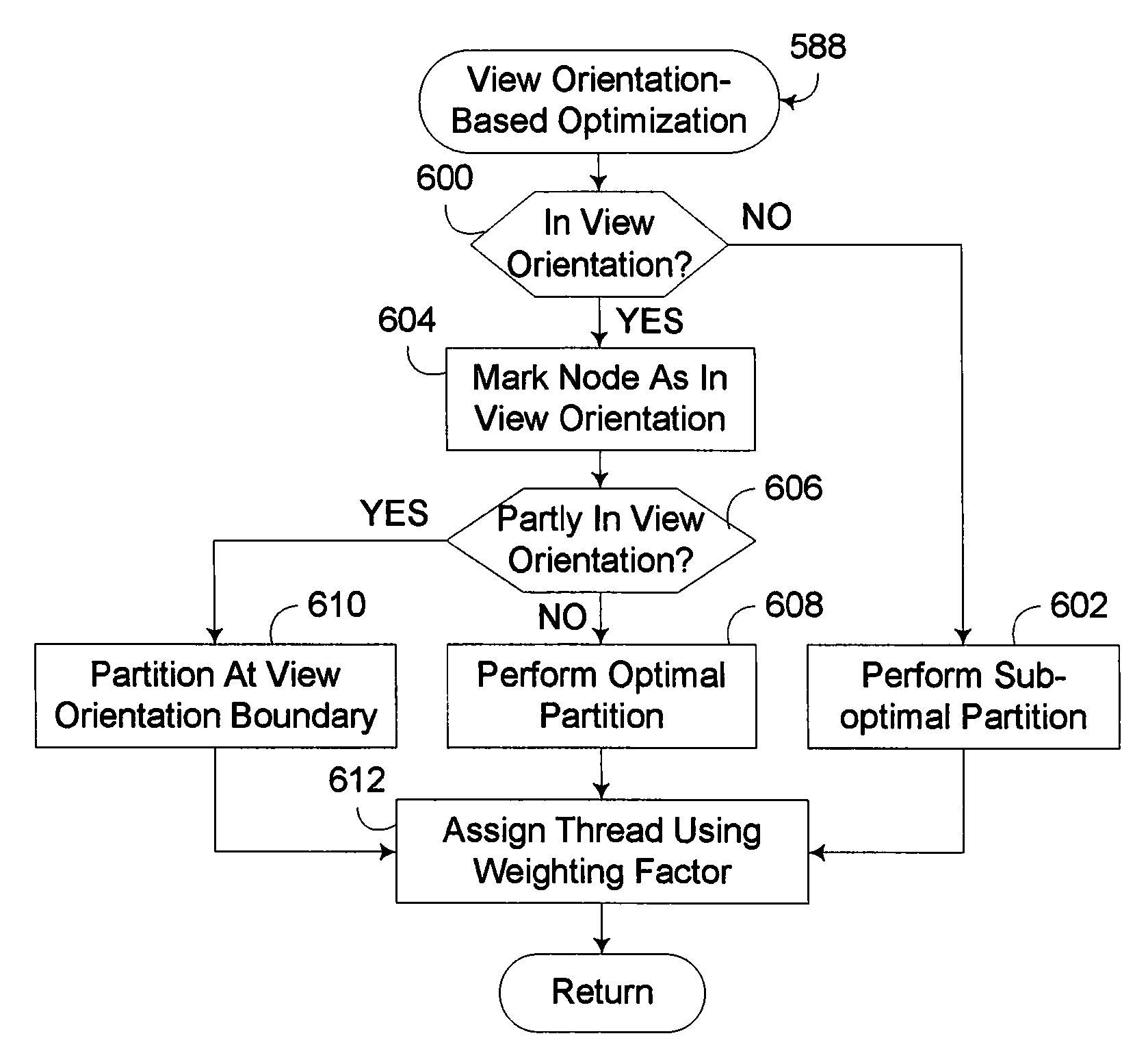
[0044]Embodiments consistent with the invention utilize the known view orientation for an image frame being rendered to optimize the generation and / or use of an accelerated data structure (ADS) used in physical rendering-based image processing. As noted above, ray tracing and other physical rendering techniques have significant benefits over rasterization in terms of image quality and scalability, and are increasingly viable options for real time image processing. Such techniques are also highly suited towards parallelization, at least with respect to the utilization of an ADS. The generation of an ADS, however, can become a performance bottleneck, and as a result, any techniques for reducing the processing overhead associated with generating an ADS can have a significant impact on rendering performance.

[0045]A view orientation consistent with the invention may be defined in a number of manners consistent with the invention, and generally is related to the visible area of a scene th...


PUM


Abstract

A circuit arrangement, program product and method utilize the known view orientation for an image frame to be rendered to optimize the generation and/or use of an Accelerated Data Structure (ADS) used in physical rendering-based image processing. In particular, it has been found that while geometry primitives that are not within a view orientation generally cannot be culled from a scene when a physical rendering technique such as ray tracing is performed, those primitives nonetheless have a smaller impact on the resulting image frame, and as a result, less processing resources can be applied to such primitives, leaving greater processing resources available for processing those primitives that are located within the view orientation, and thereby improving overall rendering performance.

Description

CROSS-REFERENCE TO RELATED APPLICATIONS[0001]This application is related to U.S. patent application Ser. No. ______, filed on even date herewith by Dave Fowler et al. and entitled “ACCELERATED DATA STRUCTURE POSITIONING BASED UPON VIEW ORIENTATION,” (ROC920070370US1) which application is incorporated by reference herein in its entirety.FIELD OF THE INVENTION[0002]The invention is generally related to data processing, and in particular to graphical imaging processing and rendering.BACKGROUND OF THE INVENTION[0003]The process of rendering two-dimensional images from three-dimensional scenes is commonly referred to as image processing. As the modern computer industry evolves image processing evolves as well. One particular goal in the evolution of image processing is to make two-dimensional simulations or renditions of three-dimensional scenes as realistic as possible. One limitation of rendering realistic images is that modern monitors display images through the use of pixels.[0004]A ...

Claims


Application Information

Patent Timeline
IPC IPC(8): G06K9/36G06T15/20
CPCG06T15/06G06T17/005G06T15/40
Inventor FOWLER, DAVID K.MEJDRICH, ERIC O.SCHARDT, PAUL E.SHEARER, ROBERT A.
Owner IBM CORP
Why Eureka
Try Eureka