Dynamically reconfigurable optical pattern generator module useable with a system to rapidly reconstruct three-dimensional data

a technology of optical pattern generator and dynamic reconstruction, which is applied in the field of dynamic reconstruction of optical pattern generator module with a system, can solve the problems of high cost of imaging system, unsuitable battery-operated portable use, and inability to compute real-time stereo matching data, etc., and achieves robust and efficient detection, low power consumption, and augment parallax information

Active Publication Date: 2016-04-26
PACKSIZE
View PDF9 Cites 73 Cited by
  • Summary
  • Abstract
  • Description
  • Claims
  • Application Information

AI Technical Summary

Benefits of technology

[0012]The present invention provides a compact, low power consumption pattern projection system that creates and projects at least first and second patterns sequentially onto a scene that includes target objects. Depending upon the embodiment, the system may be used to scan the target object, or may be used to acquire and recognize gestures made by the target object, which typically is at least part of a human making the gestures. The patterns falling upon target objects can augment parallax information when the s...

Problems solved by technology

However TOF imaging systems can be expensive and may be unsuitable for battery operated portable use due to their large form factor and substantial operating power requirements.
But three-dimensional space/time reconstruction algorithms commonly used with such systems are not very useful when imaging dynamic scenes.
This is because stereo matching must confront fundamental problems associated with triangulation, and more challengingly with correspondence estimation, which is associating points between images of the same scene acquired by the two spaced-apart two-dimensional cameras.
In practice, the imaged scene may change too fast for real-time stereo matching data to be computed.
But while this approach may work with fairly stationary images, it is difficult in practice to carry out real-time computations needed to reconstruct three-dimensional data where object(s) in the imaged scene are dynamic rather than stationary.
However, the output pattern is immutable and cannot be changed without physically altering the internal const...

Method used


Image

  • Dynamically reconfigurable optical pattern generator module useable with a system to rapidly reconstruct three-dimensional data
  • Dynamically reconfigurable optical pattern generator module useable with a system to rapidly reconstruct three-dimensional data
  • Dynamically reconfigurable optical pattern generator module useable with a system to rapidly reconstruct three-dimensional data

Examples


Embodiment Construction

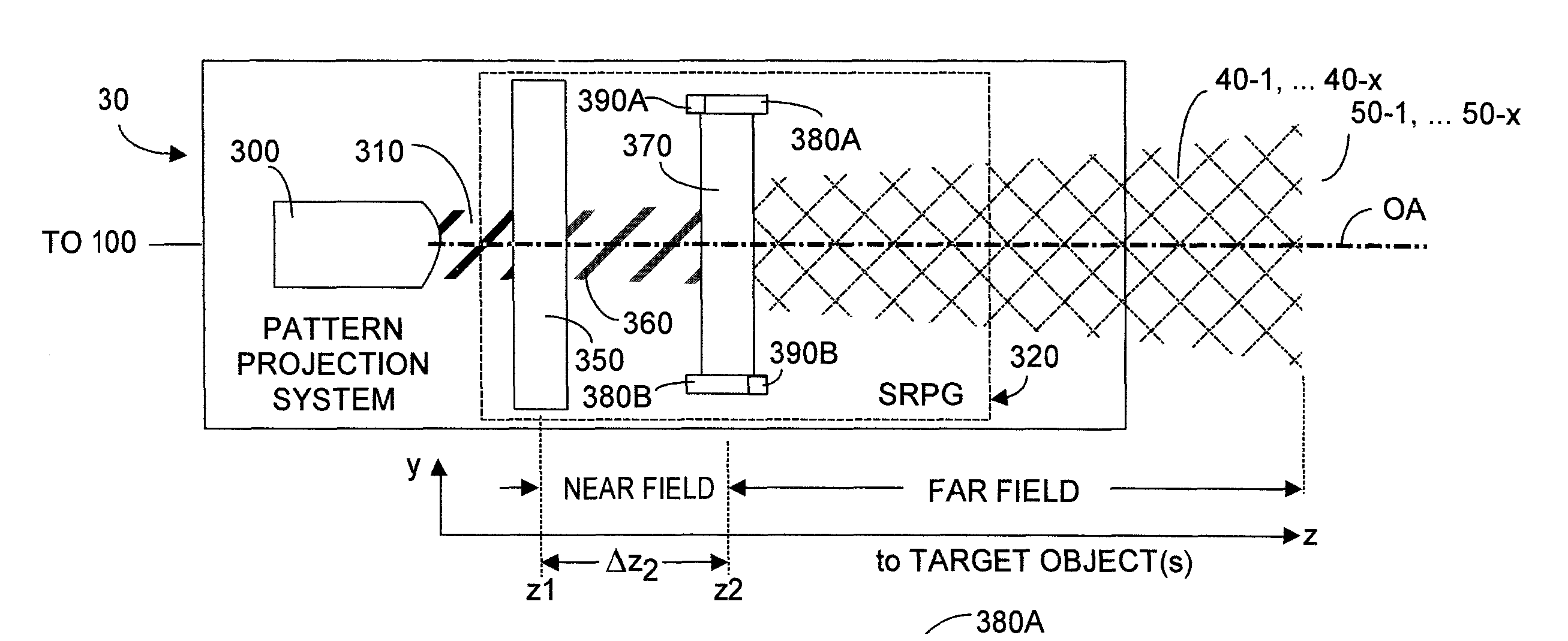
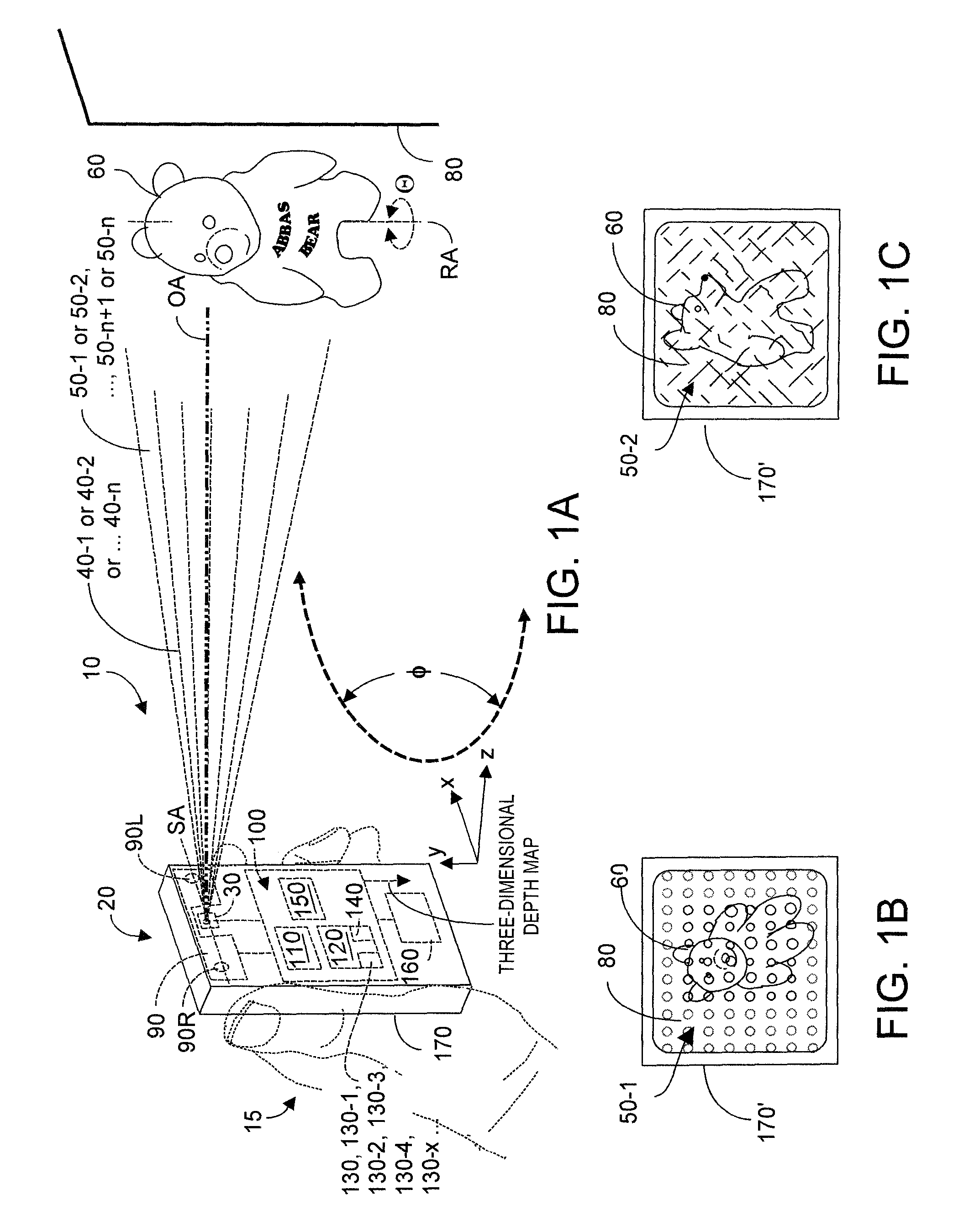
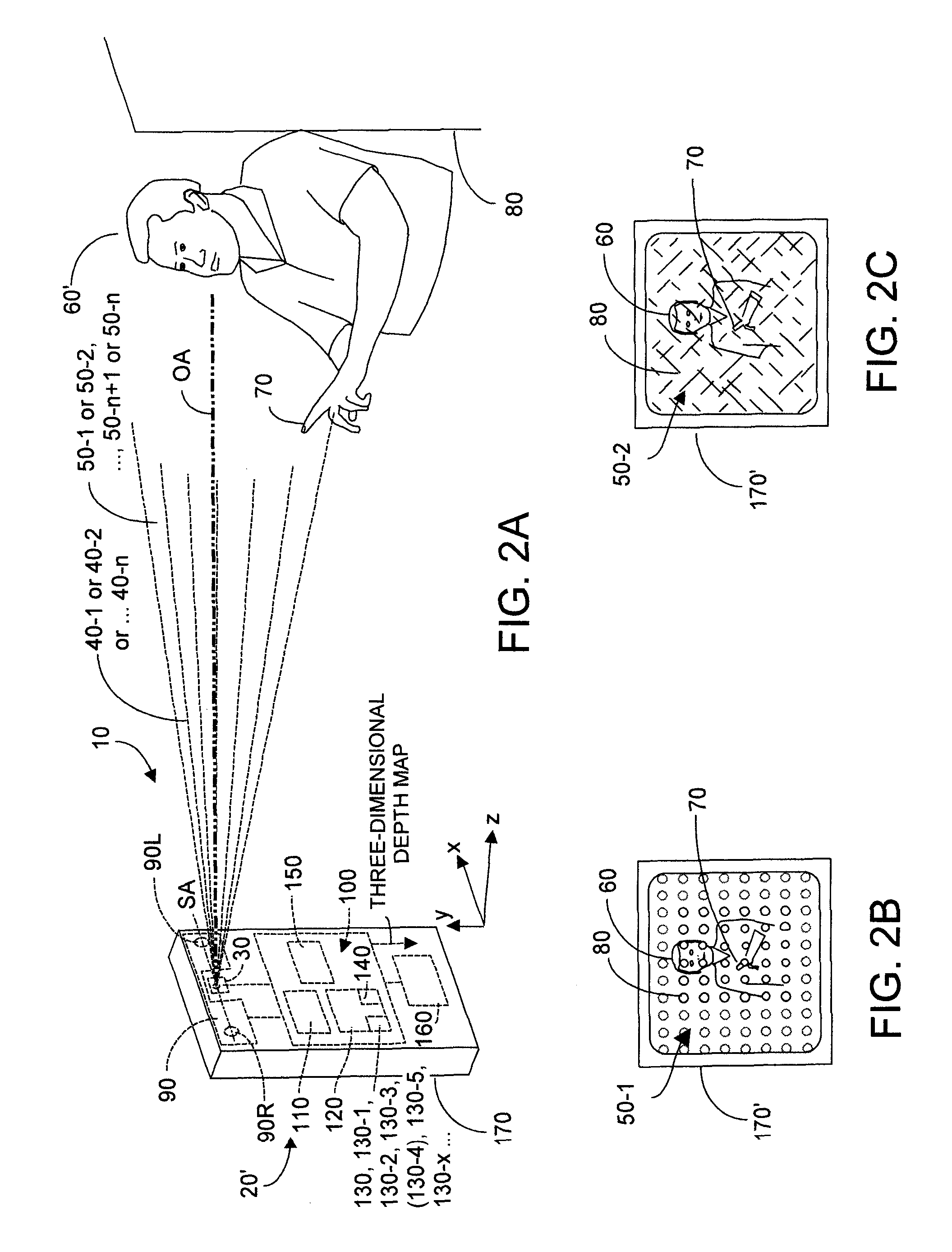
[0028]FIG. 1A depicts a system 10, which according to embodiments of the present invention preferably is handholdable by a user 15 (drawn in phantom to avoid cluttering the figure) and includes a portable preferably battery powered device 20 that houses a pattern projection system 30 that includes a light source and a spatially reconfigurable pattern generator (SRPG). Pattern projection system 30 projects an optical field 40 including at least one pattern e.g., 50-1 or 50-2 or 50-3 . . . 50-n onto a scene shown here as including a first target object 60 (a stuffed teddy bear toy) having a rotational axis denoted RA, and background imagery 80, here a planar wall. An optical axis OA is defined by system 30. Also housed within device 20 is an optical acquisition system 90, shown here as including first and second two-dimensional cameras 90L and 90R, preferably disposed on a common x-axis with output optical energy emitted from projection system 30. Cameras 90L and 90R may have RGB colo...


PUM


Abstract

Dynamic projection of at least first and second patterns contributes detectable disparity onto a scene that includes a target object. The scene is imaged with two-dimensional cameras whose acquired imagery includes disparity contributions whose presence enable a three-dimensional reconstruction depth map to be rapidly and accurately generated. In one embodiment coherent light is input to a first DOE within whose near range output is disposed a second DOE, whose far range output projects an image. Electronically varying effective optical distance between the two DOEs varies the pattern projected from the second DOE. A processor system and algorithms enable dynamic intelligent selection of projected patterns to more readily discern target object characteristics: shape, size, velocity. Patterns can implement spatio-temporal depth reconstruction, spatio-temporal depth reconstruction, and even single-camera spatio-temporal light coding reconstruction. Target objects may be scanned or may make gestures that are rapidly detected and recognized by the system and method.

Description

PRIORITY TO CO-PENDING APPLICATION[0001]Priority is claimed from applicants U.S. provisional patent application Ser. No. 62 / 022,086 filed 8 Jul. 2014 entitled “Fast Multi-Pattern Generation System for 3D Reconstruction”. Said provisional patent application is incorporated herein in full by reference.FIELD OF THE INVENTION[0002]The present invention relates generally to two-dimensional systems and methods to rapidly capture high quality depth maps of an imaged scene within a video stream. The captured data is used preferably in real-time to reconstruct three-dimensional (x,y,z) image data. In some applications the system is rotated relative to a target object so as to scan and acquire an (x,y,z) set of coordinates representing the surface of the scanned target object. In other applications, the system is stationery and captures imagery of a target object that may move. In such applications the (x,y,z) data is used to identify target objects in the imaged scene, and any gestures made ...

Claims


Application Information

Patent Timeline
IPC IPC(8): H04N13/02G06K9/00G06V10/145H04N13/239
CPCH04N13/0271H04N13/0239H04N13/0253H04N13/0296G06K9/00335G01B11/2513G01B11/2545G06T7/521H04N13/254H04N13/271H04N13/296H04N13/239G06V40/107G06V10/145G06V40/20H04N23/11G02B27/4227G02B27/4272G06T2207/10028
Inventor HAZEGHI, ARYANDAL MUTTO, CARLORAFII, ABBASDEMIRDJIAN, DAVID
Owner PACKSIZE
Why Eureka
Try Eureka