Robust Location Detection Based on Identifying Codes

a location detection and code technology, applied in the direction of instruments, measurement devices, electrical appliances, etc., can solve the problems of increasing computational complexity, no standard of comparison for the minimum required number of beacons, and difficulty in deciding whether an identifying code obtained from such a search is efficient or not, so as to increase the robustness of the location detection system

Inactive Publication Date: 2009-10-22
NOKIA CORP
View PDF0 Cites 10 Cited by
  • Summary
  • Abstract
  • Description
  • Claims
  • Application Information

AI Technical Summary

Benefits of technology

[0070]According to an embodiment of the location detection system of the second aspect of the present invention, at least one beacon of said location detection system at least occasionally checks operability of at least one other beacon of said location detection system. In a Bluetooth-based system, beacon...

Problems solved by technology

However, apart from the fact that determination of a suited identifying code may grow quite computationally complex, in particular for large graphs, it is generally hard to decide if an identifying code obtained from such a search is efficient or not, with efficiency being relat...

Method used


Image

  • Robust Location Detection Based on Identifying Codes
  • Robust Location Detection Based on Identifying Codes
  • Robust Location Detection Based on Identifying Codes

Examples


Embodiment Construction

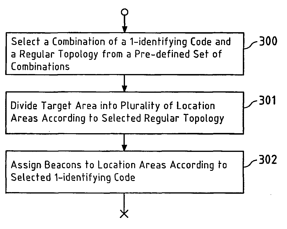
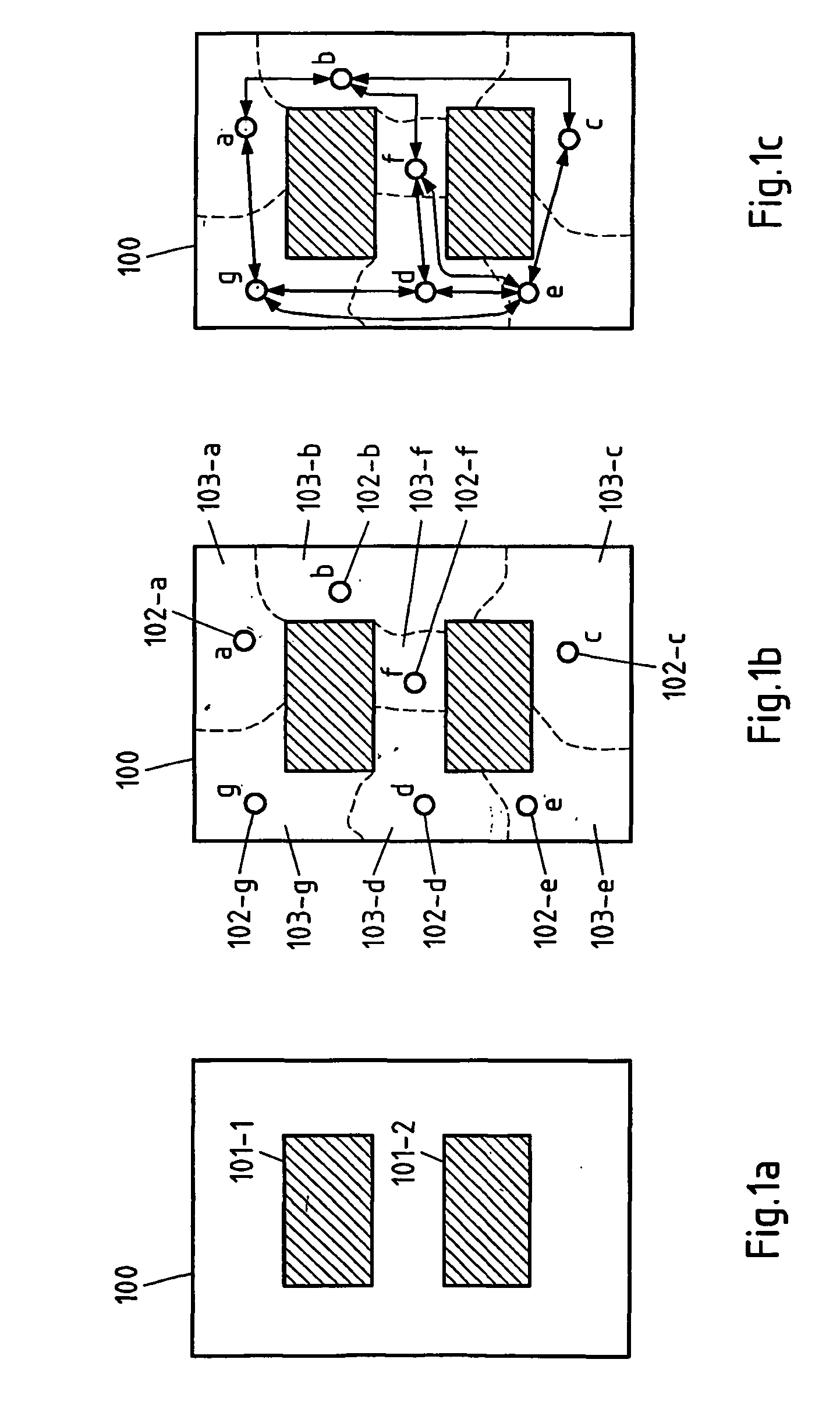
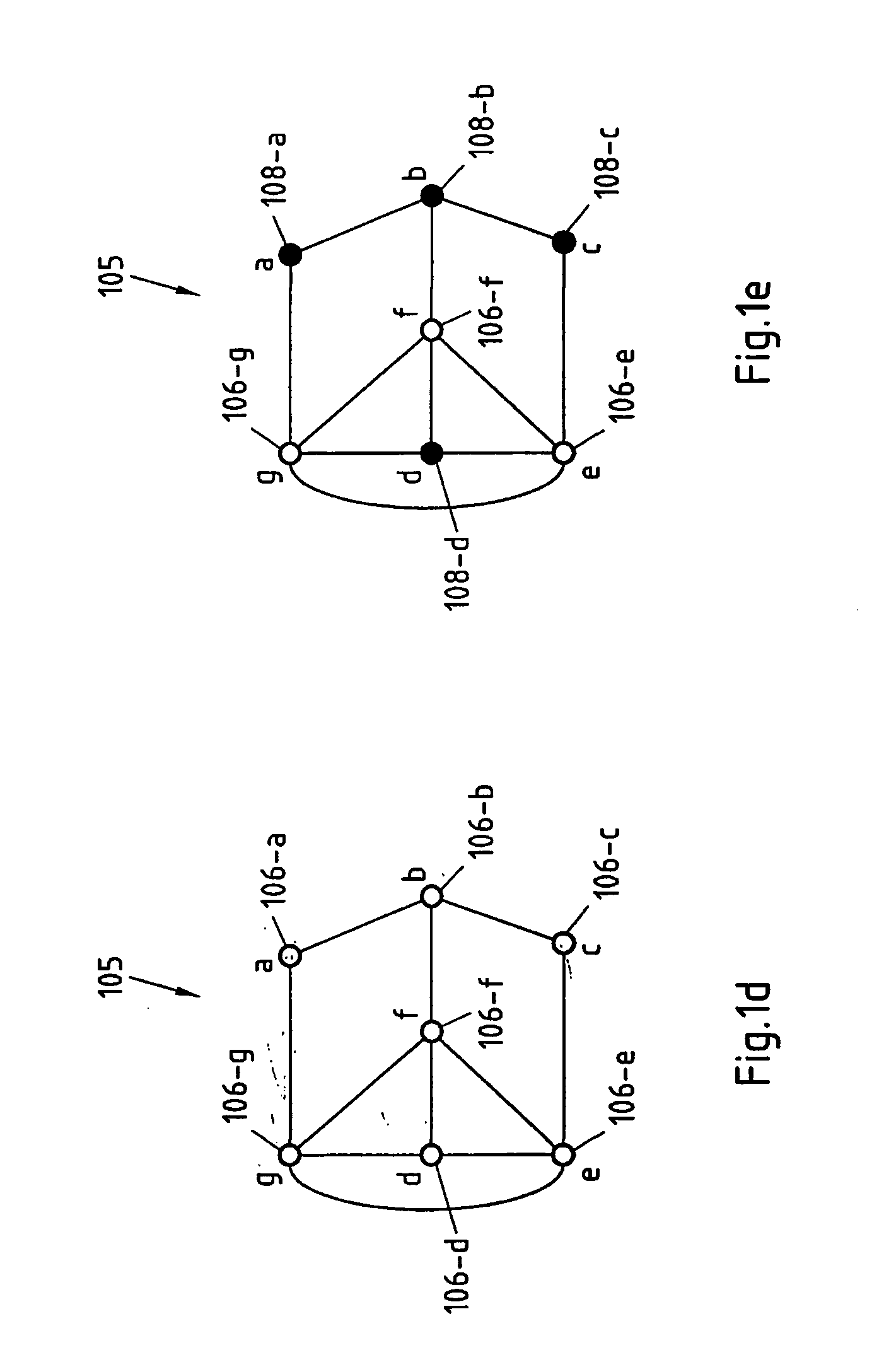
[0097]In this invention, the theory of “robust identifying codes” is applied in order to robustly locate a target in a target area of a location detection system. To this end, a plurality of beacons is distributed across the target area of the location detection system. The key concept of robust location detection is to construct a solution space that allows one to identify the location area of a target by simply noting the unique subset of beacons that can detect it. Each beacon reports a “1” if it detects a specific target and a “0” if it does not. The concatenation of these 1-bit reports at a target location detection unit forms a codeword that may be used in order to uniquely identify the location area of the target (If several targets are to be located, the 1-bit reports of the beacons may be associated with according IDs of the targets to enable the target location detection unit to differentiate the targets). This solution is also designed to be robust so that it can still pr...


PUM


Abstract

Positioning beacons (109-a . . . 109-d; 602-1 . . . 602-K) are shown in a target area (100) of a location detection system (600) with location areas (103-a . . . 103-g) in the target area associated with potential beacon positions (102-a . . . 102-g) and represented by vertices (106-a . . . 106-g) of a graph (105). Reliable connectivity between location areas is represented by edges between vertices that represent the location areas. The beacons are assigned to location areas of a subset of vertices of the graph, which subset represents a robust 1-identifying code. The graph may be constrained to a regular topology to exploit availability of optimum or close-to-optimum t-edge-robust and t-vertex-robust 1-identifying codes for such regular topologies. A greedy search algorithm (400-425) may be used to find a small subset of vertices representing t-vertex-robust 1-identifying codes.

Description

CROSS-REFERENCE TO RELATED APPLICATION[0001]The application is the U.S. National Stage of International Application Number PCT / IB2005 / 002708 filed Sep. 13, 2005.FIELD OF THE INVENTION[0002]This invention relates to methods, software applications and software application products for positioning beacons in target areas of location detection systems, and to such location detection systems themselves.BACKGROUND OF THE INVENTION[0003]Document “Grid coverage for surveillance and target location in distributed sensor networks” by Chakrabarty, K., Iyengar, S. S., Qi, H. and Cho, E., IEEE Transactions on Computers, Vol. 51, Issue 12, December 2002, pp. 1448-1453 introduces “identifying codes” as a method to uniquely identify faulty processors in multiprocessor systems.[0004]Microprocessors are generally arranged in regular topologies (such as hyper-cubes, meshes, etc.). In order to detect faults, some of the processors must serve as both processing units as well as fault detection units wit...

Claims


Application Information

Patent Timeline
IPC IPC(8): H04B7/00G01S5/02
CPCG01S5/02H04W16/18H04W16/00
Inventor GREEN, MARILYNNWANG, SHU-SHAW
Owner NOKIA CORP
Why Eureka
Try Eureka