Implantable lead management

a lead management and implant pocket technology, applied in the direction of coupling device details, coupling device connection, therapy, etc., can solve the problems of lead abrasion and increase the likelihood of lead abrasion, so as to reduce the size of the implant pocket, improve the flex life performance, and reduce the risk of lead abrasion

Active Publication Date: 2010-09-23
MEDTRONIC INC
View PDF6 Cites 5 Cited by
  • Summary
  • Abstract
  • Description
  • Claims
  • Application Information

AI Technical Summary

Benefits of technology

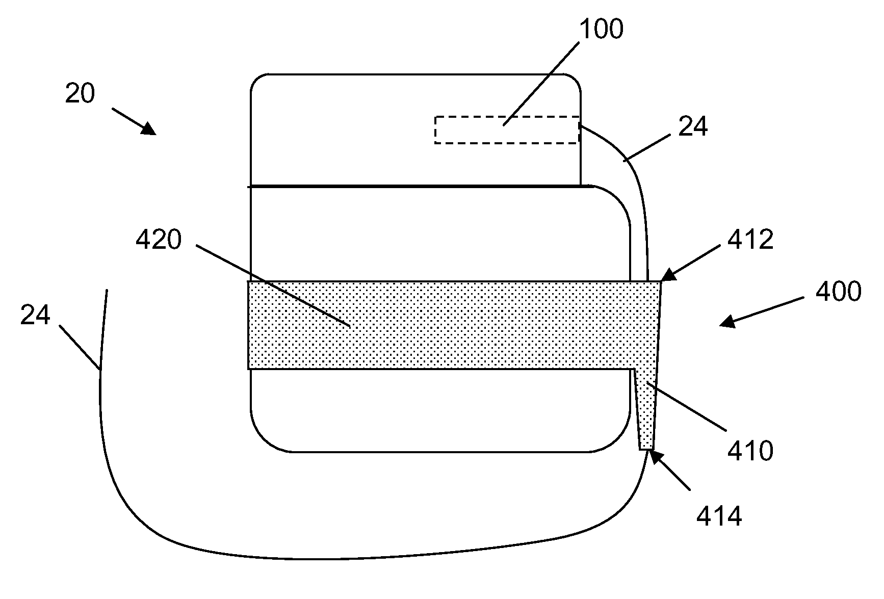
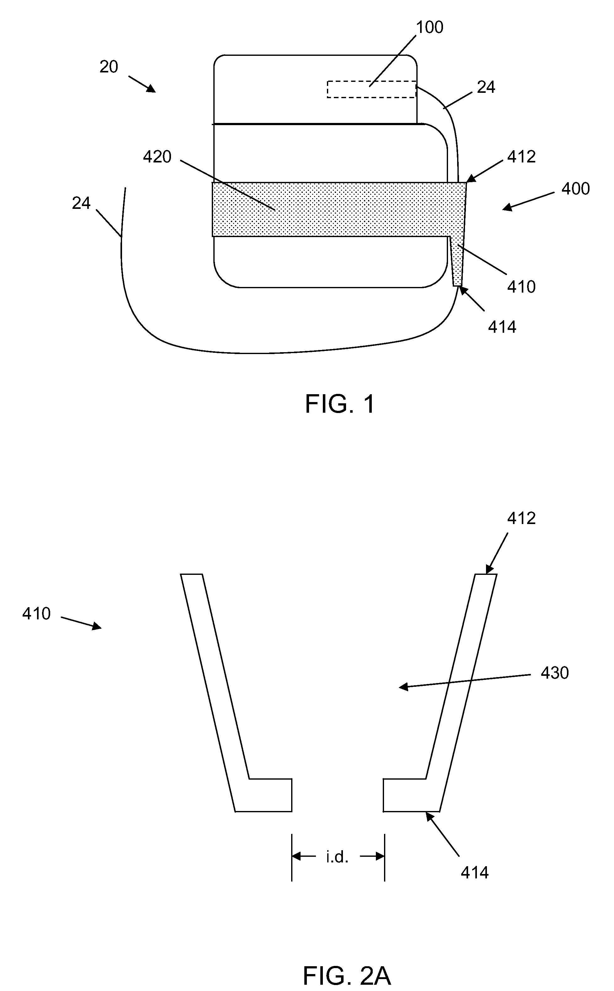
[0005]Apparatuses for managing excess lead length in proximity to an implanted medical device are described herein. The apparatuses may improve flex life performance, reduce lead abrasion, or may decrease the size of the implant pocket.

Problems solved by technology

Problems with lead abrasion may be exacerbated with rechargeable active implantable medical devices and excess coiled lead.
If the coiled excess lead or a portion of the lead crosses the face of the device between the device and the patient's skin, the likelihood of lead abrasion may increase.
Because the primary recharge coil of an external recharge head is placed adjacent the patient's skin in a location over the implanted device, the lead may be impacted between the recharge head and the implanted device causing abrasion of the lead.

Method used


Image

  • Implantable lead management
  • Implantable lead management
  • Implantable lead management

Examples


Embodiment Construction

[0024]In the following detailed description, reference is made to the accompanying drawings that form a part hereof, and in which are shown by way of illustration several specific embodiments of devices, systems and methods. It is to be understood that other embodiments are contemplated and may be made without departing from the scope or spirit of the present disclosure. The following detailed description, therefore, is not to be taken in a limiting sense.

[0025]All scientific and technical terms used herein have meanings commonly used in the art unless otherwise specified. The definitions provided herein are to facilitate understanding of certain terms used frequently herein and are not meant to limit the scope of the present disclosure.

[0026]As used in this specification and the appended claims, the singular forms “a”, “an”, and “the” encompass embodiments having plural referents, unless the content clearly dictates otherwise. As used in this specification and the appended claims, ...


PUM


Abstract

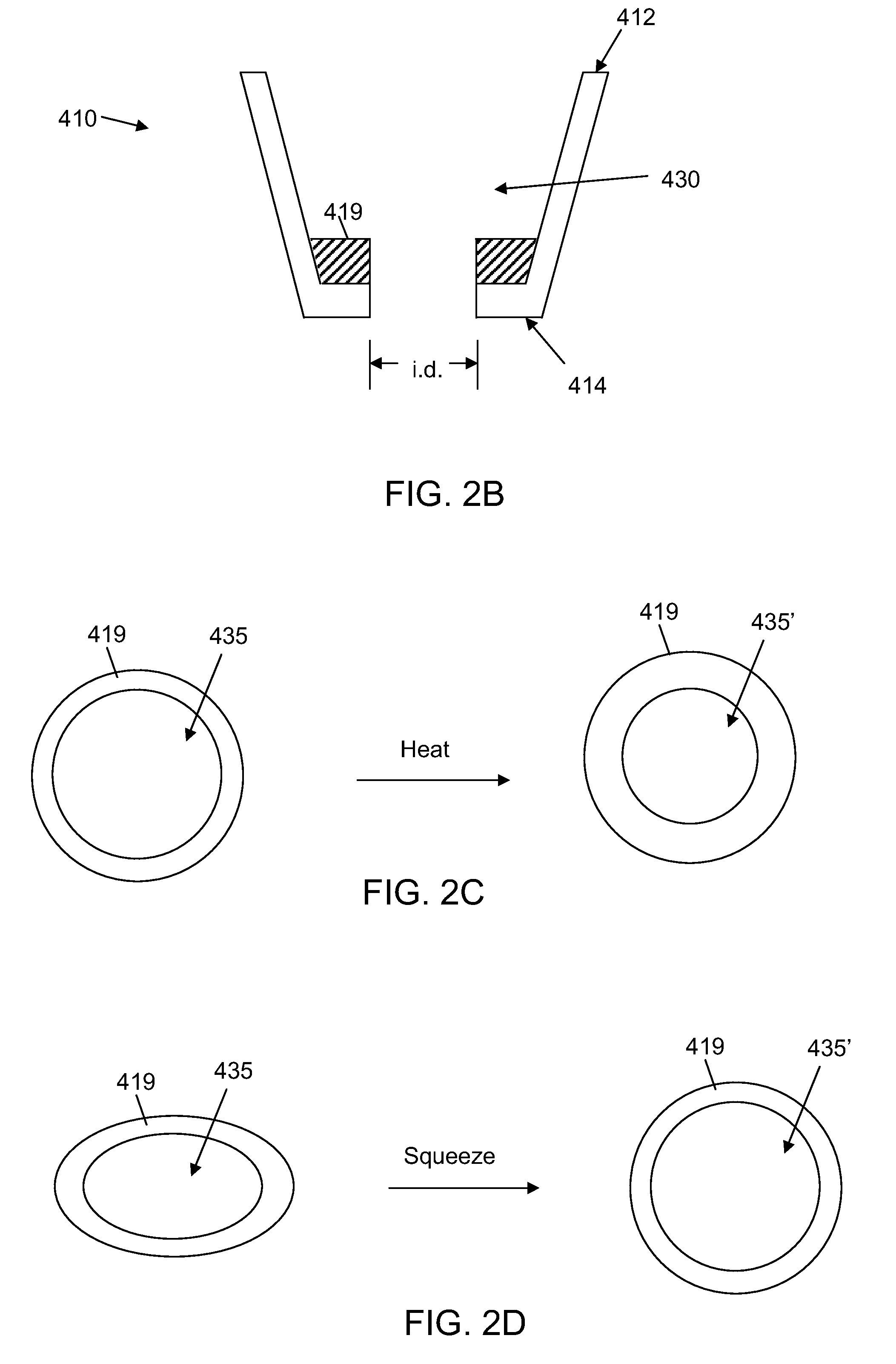
An apparatus for managing a lead of an implantable medical device includes a lead retention element and a fixation element. The lead retention element has a proximal end, a distal end, and a lumen extending from the proximal end to the distal end. The lumen is configured to slidably receive the lead. The fixation element is configured to fix the lead retention element relative to the implantable medical device in an orientation orthogonal to a lead receptacle of the device such that the proximal end of the lead retention element is closer to an opening of the lead receptacle than the distal end of the retention element. The distal end of the lead retention element is configured to firmly engage the lead to resist proximal sliding of the lead in the lumen of the retention element once the lead has been moved distally through the lumen.

Description

CROSS-REFERENCE TO RELATED APPLICATIONS[0001]The present application claims priority from U.S. Provisional Patent Application No. 61 / 161,906, filed Mar. 20, 2009, the entire disclosure of which is incorporated herein by reference.FIELD[0002]This application relates to implantable medical devices, more particularly devices employing medical leads and apparatuses for managing implanted leads.BACKGROUND[0003]Implantable medical devices are used to treat a variety of diseases, and their use is increasing. Many implantable medical devices employ medical leads to deliver electrical therapy to a patient or to monitor patient parameters. The leads are connected to the active device, which is typically implanted subcutaneously in the patient, and extend from the implanted device to a target location of the patient. The leads typically have a length greater than needed to extend from the device to the target location to ensure that the lead will be of sufficient length for almost all patients...

Claims


Application Information

Patent Timeline
Patent Type & Authority Applications(United States)
IPC IPC(8): A61N1/04
CPCA61N1/05H01R2201/12H01R13/5804A61N1/375
Inventor DEININGER, STEVE T.KAST, JOHN E.MCMULLEN, RAYMOND F.
Owner MEDTRONIC INC
Why Eureka
Try Eureka