Ion generating system for using in a vehicle

Inactive Publication Date: 2010-09-23
PANASONIC CORP
View PDF19 Cites 19 Cited by
  • Summary
  • Abstract
  • Description
  • Claims
  • Application Information

AI Technical Summary

Benefits of technology

[0004]The invention is achieved to solve the above problem. An object of this invention is to provide an ion generating system for effectively removing th

Problems solved by technology

However, users strongly smell the odor of the vehicle when the users get inside

Method used


Image

  • Ion generating system for using in a vehicle
  • Ion generating system for using in a vehicle
  • Ion generating system for using in a vehicle

Examples


Example

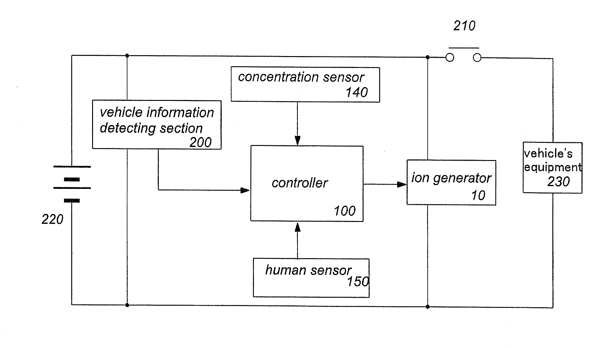
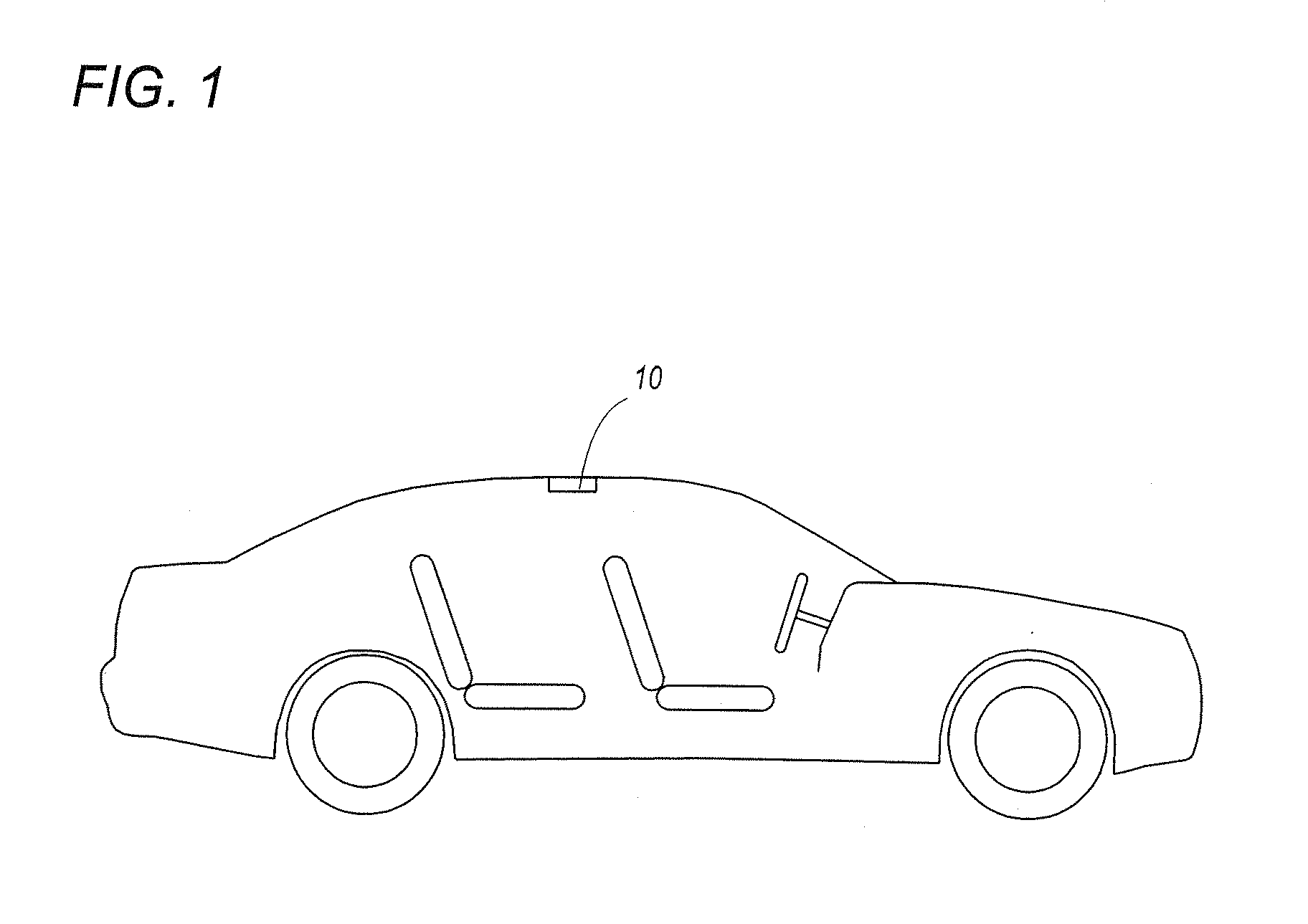
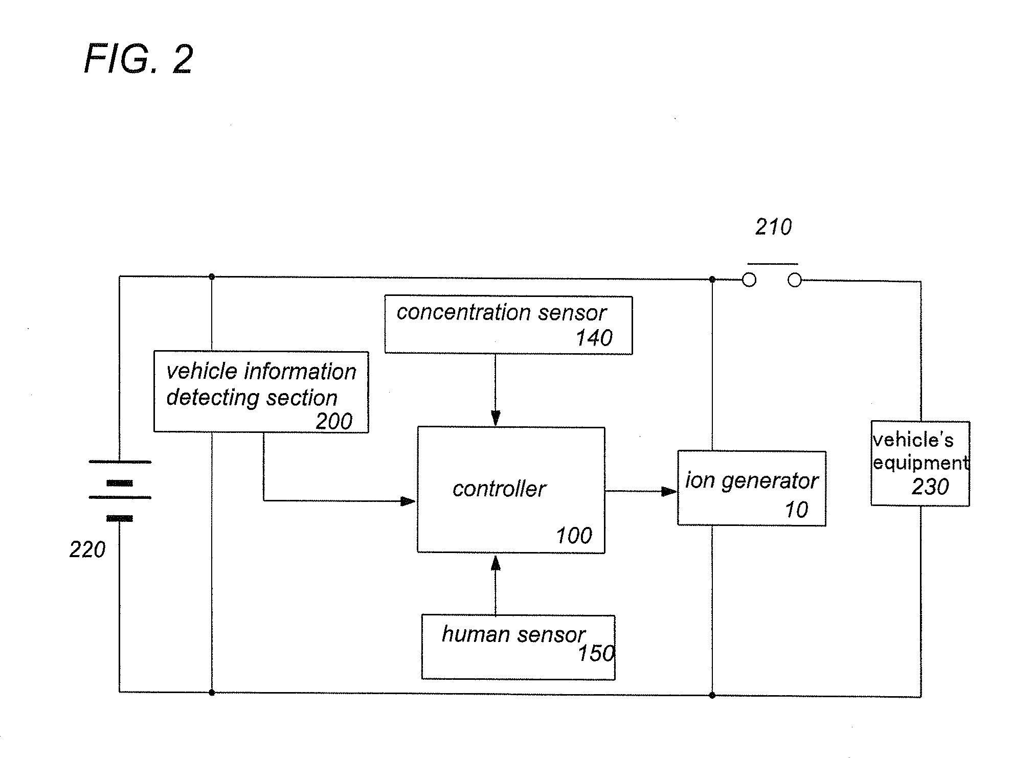
[0047]An ion generation system for using in the vehicle in this invention is provided for being incorporated into a vehicle. The ion generating system comprises an ion generator 10 and a controller 100. The controller 100 controls operation of the ion generator 10. The ion generator 10 is, for example, disposed on the ceiling of a vehicle interior shown in FIG. 1 to dispense ion to passenger's room. However, it is possible to dispose the ion generator at an air outlet of an air conditioner.

[0048]As shown in FIG. 3, the ion generator 10 comprises an emitter electrode 20, an opposed electrode 30, a heat exchanger 40, and an atomizing barrel 50. The atomizing barrel 50 is configured to hold the emitter electrode 20, the opposed electrode 30, and the heat exchanger 40. the emitter electrode 20 is disposed in the atomizing barrel and is aligned with an central axis of the atomizing barrel 50. The emitter electrode 20 has its rear end fixed to a bottom wall 51 of the atomizing barrel 50 a...


PUM


Abstract

An ion generating system for use in a vehicle has an ion generator and a controller for controlling the operation thereof. The ion generator is energized by a vehicle battery to keep dispensing ions by means of the controller even under a condition where the engine is not running, making deodorization or sterilization of a passenger's room to give a comfortable environment to the vehicle.

Description

TECHNICAL FIELD[0001]This invention relates generally to an ion generating system for using in a vehicle. More particularly, this invention relates to an ion generating system which is incorporated into a vehicle, and which is configured to generate ion which is dispensed to the vehicle interior for removing odor.BACKGROUND ART[0002]Japanese Patent Application Publication No. 2006-151046 discloses an ion generator which is attached to the vehicle for sending negative ion to the vehicle interior to remove the bad odor and sterilize the bacteria in the vehicle. In the case where the ion generator is incorporated into the vehicle, the ion generator receives an electrical power from the vehicle's battery and is configured to operate when an ignition switch is turned on. In substance, the ion generator is configured to generate the ion only when an engine is running.[0003]However, users strongly smell the odor of the vehicle when the users get inside the vehicle. Therefore, the users fee...

Claims


Application Information

Patent Timeline
IPC IPC(8): G06F7/00
CPCB60H1/00735B60H3/0071H01T23/00B60H2003/026B60H3/022
Inventor AKISADA, SHOUSUKESUGAWA, AKIHIDEYANO, TAKESHIOBATA, KENJIOKUDE, AKIO
Owner PANASONIC CORP
Why Eureka
Try Eureka