Combined heat and power cycle system

a heat and power cycle system and heat recovery technology, applied in steam engine plants, machines/engines, mechanical equipment, etc., can solve the problems of large amounts of waste heat simply dumped into the atmosphere, oxides and particulates may be emitted, and conventional heat recovery systems do not operate with sufficient efficiency to make energy recovery cost-effective,

Inactive Publication Date: 2010-09-30
GENERAL ELECTRIC CO
View PDF16 Cites 81 Cited by
  • Summary
  • Abstract
  • Description
  • Claims
  • Application Information

AI Technical Summary

Benefits of technology

[0007]In accordance with one exemplary embodiment disclosed herein, a combined heat and power cycle system including at least two integrated rankine cycle systems is provided. The combined heat and power cycle system includes a heat generation system comprising at least two separate heat sources having different temperatures. The combined heat and power cycle system includes a first rankine cycle system coupled to a first heat source among the at least two separate heat sources and configured to circulate a first working fluid. The first rankine system is configured to remove heat from the first heat source. A second rankine cycle system is coupled to at least one second heat source among the at least two separate heat sources and configured to circulate a second working fluid. The at least one second heat source includes a lower temperature heat source than the first heat source. The second rankine cycle system is configured to remove heat from the at least one second heat source. The first and second working fluids are circulatable in heat exchange relationship through a cascaded heat exchange unit for condensation of the first working fluid in the first rankine cycle system and evaporation of the second working fluid in the second rankine cycle system. At least one heat exchanger is disposed at one or more locations in the first rankine cycle system, second rankine cycle system, or combinations thereof. The first working fluid, second working fluid, or combinations thereof are circulatable in heat exchange relationship with a third fluid through the at least one heat exchanger for heating the third fluid.
[0008]In accordance with one exemplary embodiment disclosed herein, a combined heat and power cycle system including at least two integrate

Problems solved by technology

When waste heat is low grade, such as waste heat having a temperature of heat below 840 degrees Fahrenheit, for example, conventional heat recovery systems do not operate with sufficient efficiency to make recovery of energy cost-effective.
The net result is that vast quant

Method used


Image

  • Combined heat and power cycle system
  • Combined heat and power cycle system
  • Combined heat and power cycle system

Examples


Embodiment Construction

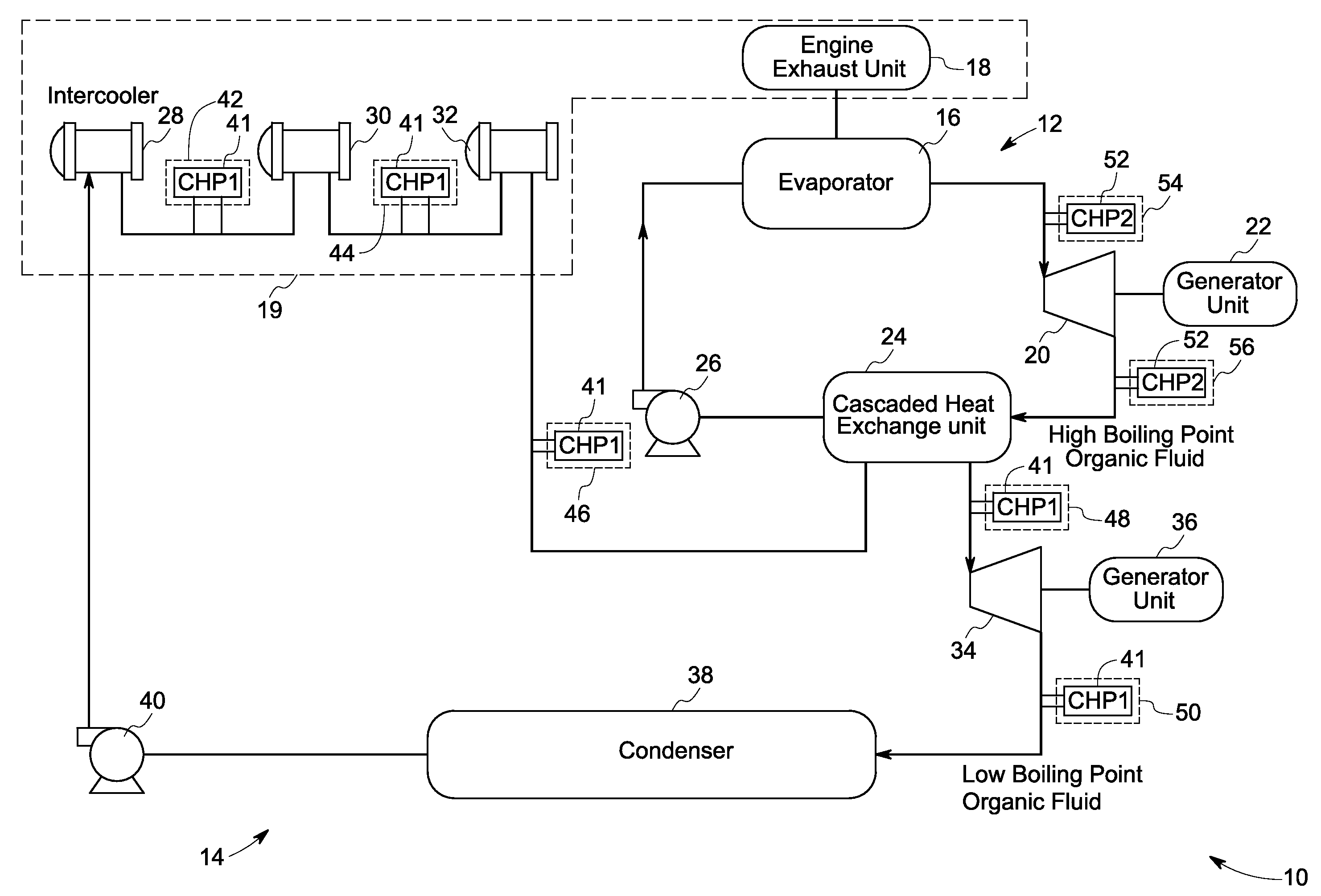
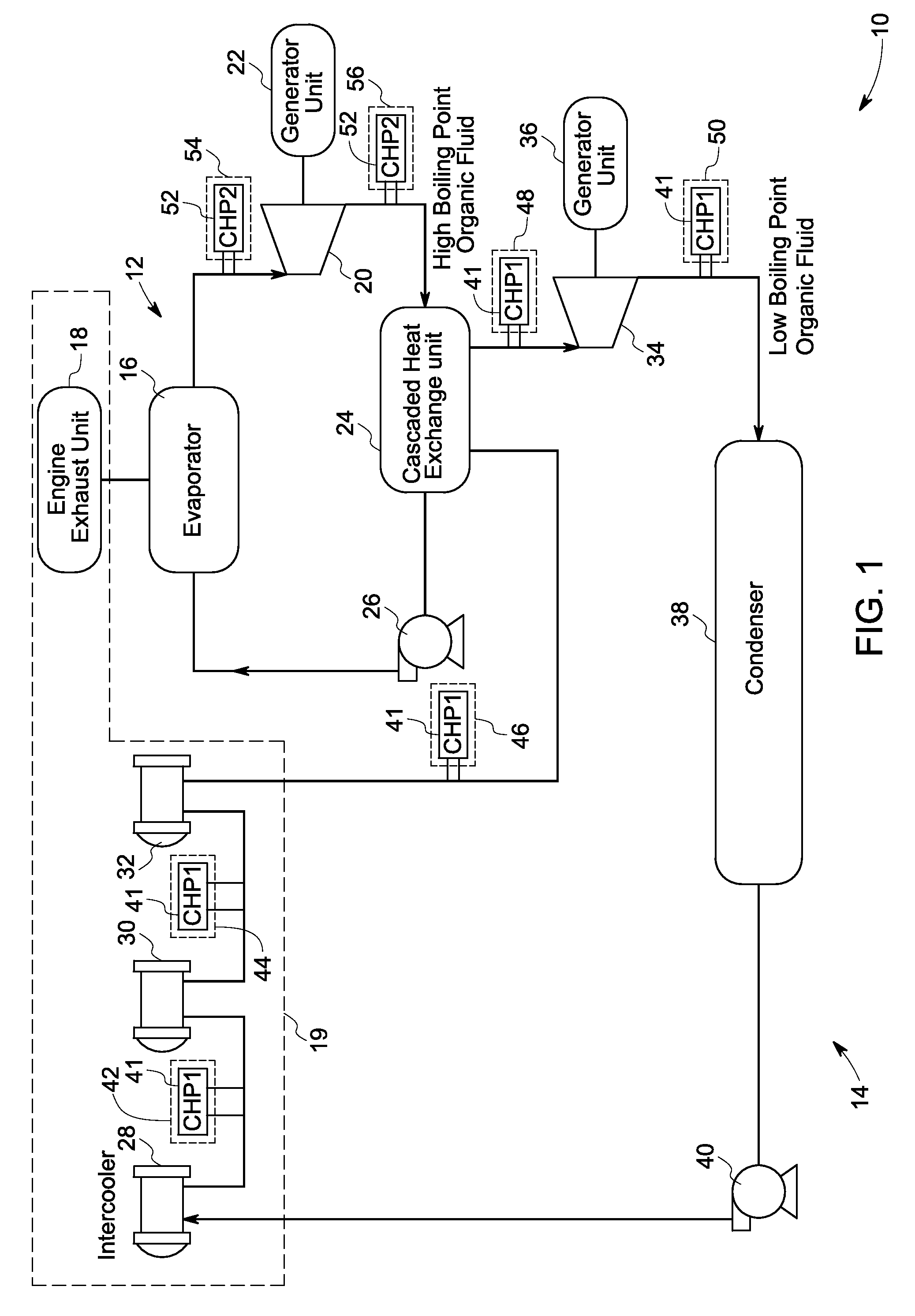
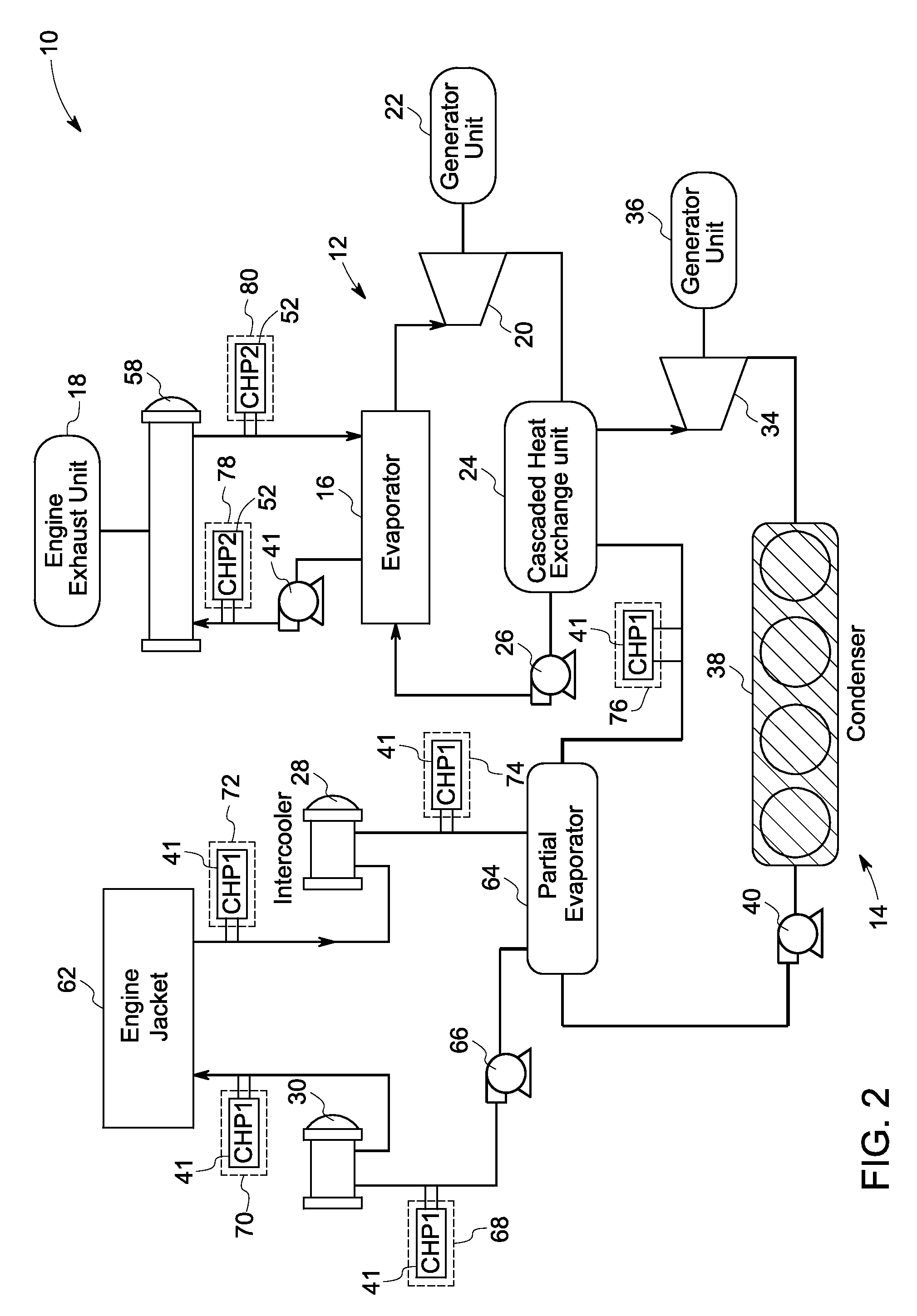
[0018]As discussed in detail below, embodiments of the present invention provide a combined heat and power cycle system having at least two integrated rankine cycle systems coupled to at least two separate heat sources respectively having different temperatures. The first rankine cycle system is coupled to a first heat source and configured to circulate a first working fluid. The second rankine cycle system is coupled to at least one second heat source and configured to circulate a second working fluid. The second heat source includes a lower temperature heat source than the first heat source. The combined heat and power cycle system also includes a cascaded heat exchange unit. The first and second working fluids are circulated in heat exchange relationship for condensation of the first working fluid in the first rankine cycle system and evaporation of the second working fluid in the second rankine cycle system. In accordance with the exemplary embodiments of the present invention, ...


PUM


Abstract

A combined heat and power cycle system includes a heat generation system having at least two separate heat sources having different temperatures. The combined heat and power cycle system includes a first rankine cycle system coupled to a first heat source among the at least two separate heat sources and configured to circulate a first working fluid. A second rankine cycle system is coupled to at least one second heat source among the at least two separate heat sources and configured to circulate a second working fluid. The first and second working fluids are circulatable in heat exchange relationship through a cascaded heat exchange unit for condensation of the first working fluid in the first rankine cycle system and evaporation of the second working fluid in the second rankine cycle system. At least one heat exchanger is disposed at one or more locations in the first rankine cycle system, second rankine cycle system, or combinations thereof.

Description

BACKGROUND[0001]The embodiments disclosed herein relate generally to the field of a combined heat and power cycle system and, more particularly, to a combined heat and power cycle system for recovering waste heat from a plurality of heat sources having different temperatures for heating purpose and generation of electricity.[0002]Enormous amounts of waste heat are generated by a wide variety of industrial and commercial processes and operations. Example sources of waste heat include heat from space heating assemblies, steam boilers, engines, and cooling systems. When waste heat is low grade, such as waste heat having a temperature of heat below 840 degrees Fahrenheit, for example, conventional heat recovery systems do not operate with sufficient efficiency to make recovery of energy cost-effective. The net result is that vast quantities of waste heat are simply dumped into the atmosphere, ground, or water.[0003]Some power generation systems provide better reliability and off-grid op...

Claims


Application Information

Patent Timeline
IPC IPC(8): F01K13/00F01K23/06
CPCF01K23/04Y02E20/14F01K25/10F01K23/065
Inventor AST, GABORFREY, THOMAS JOHANNESHUCK, PIERRE SEBASTIENKOPECEK, HERBERT
Owner GENERAL ELECTRIC CO
Why Eureka
Try Eureka