Flat plate type micro heat transport device

a heat transport device and micro-chip technology, applied in the field of flat-plate type micro heat transport devices, can solve the problems of difficult to provide a space for heat control, limit the size of heat control methods capable of being applied to various devices, etc., and achieve the effects of reducing fluid pressure drop, improving productivity, and efficient control of heat of portable electronic devices

Inactive Publication Date: 2010-09-30
ELECTRONICS & TELECOMM RES INST
View PDF15 Cites 14 Cited by
  • Summary
  • Abstract
  • Description
  • Claims
  • Application Information

AI Technical Summary

Benefits of technology

[0023]According to the present invention, there are is provided an effect of efficiently controlling heat of portable electronic devices, in which a flat plate type thin structure and vapor and liquid flow paths, separately formed, are provided, thereby removing fluid pressure drop caused by friction at an interface between vapor and a liquid in such a way that it is advantageous to high-heat flux and heat-transport for a relatively long distance.
[0024]Also, since a thickness of the flat plate type micro heat transport device is 2 mm or less, the device is suitable for subminiature portable electronic devices. Particularly, the device is very effective when an electronic package structure of a device is very narrow.
[0025]Due to a structure of coupling two plates having the same configuration and the same size, it is possible to produce plates of only one type. Accordingly, it is possible to improve productivity and reduce manufacturing costs.

Problems solved by technology

However, due to rapid changes in structures of electronic communication devices, there are a lot of limitations on sizes in heat control methods capable of being applied to various devices and it is difficult to provide a space for heat control.

Method used


Image

  • Flat plate type micro heat transport device
  • Flat plate type micro heat transport device
  • Flat plate type micro heat transport device

Examples


Embodiment Construction

[0029]Hereinafter, exemplary embodiments of the present invention will now be described in detail with reference to the accompanying drawings.

[0030]Only, in describing operations of the exemplary embodiments in detail, when it is considered that a detailed description on related well-known functions or constitutions unnecessarily may make essential points of the present invention be unclear, the detailed description will be omitted.

[0031]Also, in the drawings, the same reference numerals are used throughout to designate the same or similar components.

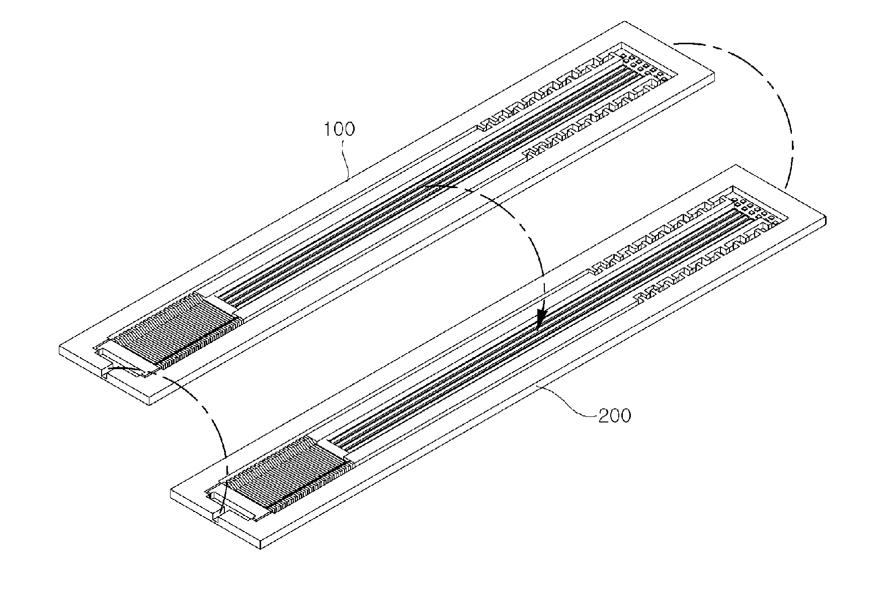
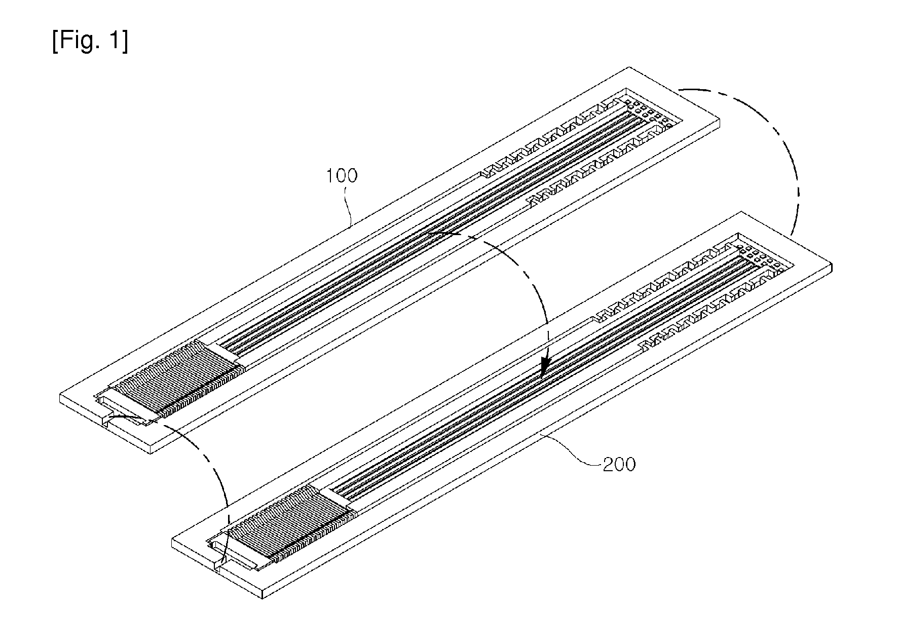
[0032]FIG. 1 is a perspective view illustrating separated top and bottom plates to show an overall structure of a flat plate type micro heat transport device according to an exemplary embodiment of the present invention.

[0033]Referring to FIG. 1, the flat plate type micro heat transport device is formed in an envelope shape having an enclosed structure including top and bottom plates 100 and 200 having the same configuration and the sam...


PUM


Abstract

There is provided a flat plate type micro heat transport device formed of two plates coupled with each other to be opposite to each other, each of which includes: a reservoir formed to store a moving fluid charged via an inlet; a evaporator formed separated from the reservoir to generate vapor having latent heat by vaporizing the moving fluid; a vapor flow path formed to be connected to the evaporator, through which the vapor having latent heat is transported; a condenser formed to be connected to the vapor flow path and to condense the vapor having latent heat; and a liquid flow path formed to be connected to the condenser and the evaporator and separately from the vapor flow path to transport a liquid obtained by condensing the vapor. The device may efficiently control heat with respect to portable electronic devices by effectively transportring heat generated by a heat source.

Description

TECHNICAL FIELD[0001]The present invention relates to a flat plate type micro heat transport device, and more particularly, to a flat plate type micro heat transport device having a thin thickness, which is driven by vapor-liquid two phase fluid mechanism.BACKGROUND ART[0002]Recently, high integration and subminiaturization of various easily portable electronic communication devices such as notebooks and sub notebooks are rapidly accelerated. Particularly, personal mobile electronic communication devices are rapidly miniaturized and become ultrathin.[0003]Such electronic communication devices keep controlling heat by providing a space for heat dissipation therein. However, due to rapid changes in structures of electronic communication devices, there are a lot of limitations on sizes in heat control methods capable of being applied to various devices and it is difficult to provide a space for heat control.[0004]As generally applied methods, there is a method in which a material havin...

Claims


Application Information

Patent Timeline
Patent Type & Authority Applications(United States)
IPC IPC(8): F28D15/04
CPCF28D15/0233F28D15/046H01L23/427H01L2924/0002H01L2924/00H05K7/20G06F1/20
Inventor MOON, SEOK HWANHWANG, GUNN
Owner ELECTRONICS & TELECOMM RES INST
Why Eureka
Try Eureka