
Method for heating a container placed on a cooktop by heating means associated to inductors

Active Publication Date: 2010-09-30
GRP BRANDT
View PDF9 Cites 30 Cited by
  • Summary
  • Abstract
  • Description
  • Claims
  • Application Information

AI Technical Summary

Benefits of technology

"The present invention provides a method for optimizing heating of a container on a cooktop without predetermined location of the cooking center. The method involves heating means associated with inductors that detect the presence of a container. The heating means form a two-dimensional array on the cooking surface. The method includes steps of searching for a heating area and calculating power delivered by each heating means based on the overall set point power and the rate of coverage of the detection means by the container. The method also takes into account movement of the container during cooking and allows for a shifted heating area. The cooktop comprises the heating means and means for executing the heating method. The technical effects of the invention include efficient heating of containers on a cooktop without the need for predetermined location and optimal power distribution."

Problems solved by technology

However, the above document remains silent on the problem of inductors partly covered by a container.

Method used


Image

  • Method for heating a container placed on a cooktop by heating means associated to inductors
  • Method for heating a container placed on a cooktop by heating means associated to inductors
  • Method for heating a container placed on a cooktop by heating means associated to inductors

Examples


first embodiment

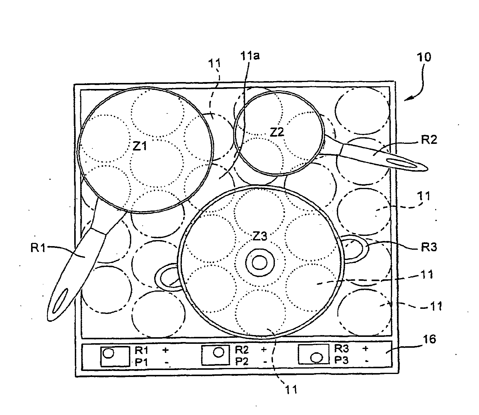
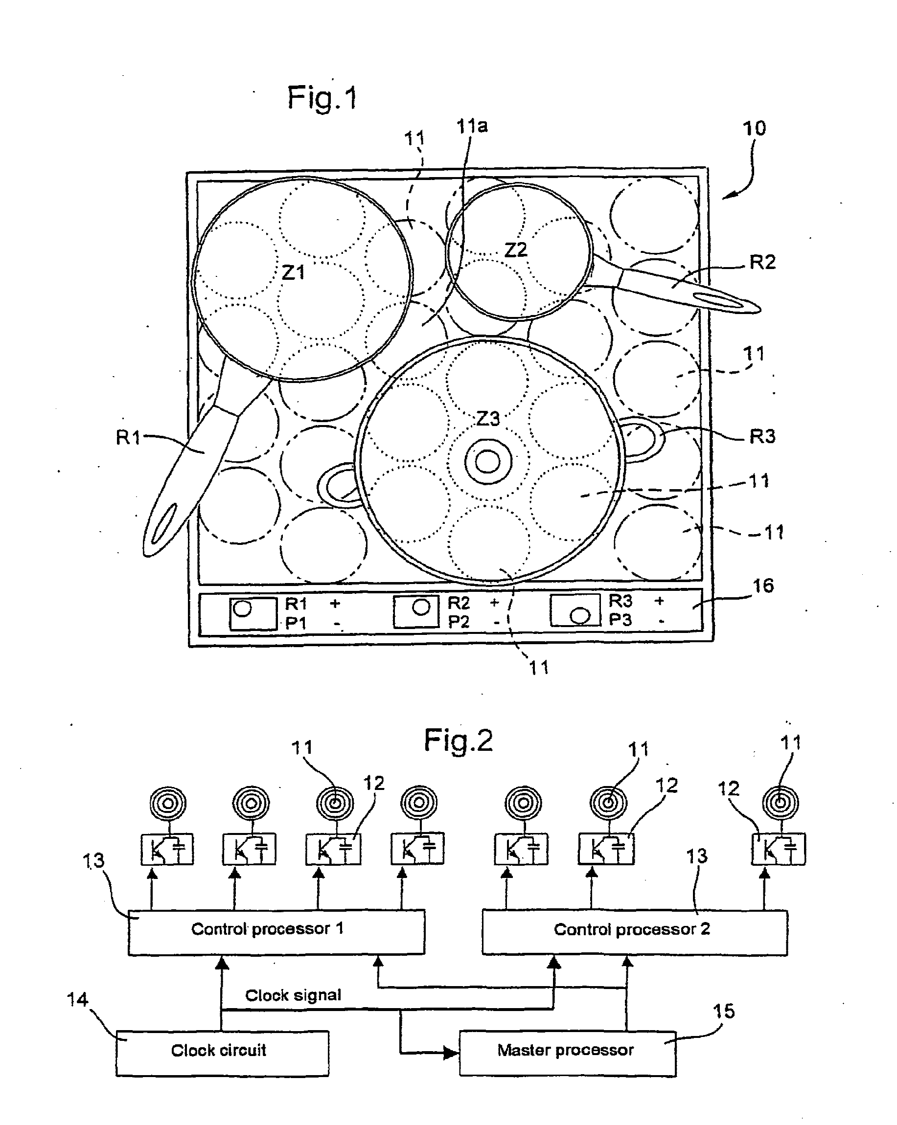
[0127]In a first embodiment, the priority is a homogeneous power density to distribute power homogeneously over the bottom of the container.

[0128]This distribution minimizes the field radiated by the partly covered inductors as the current flowing in those inductors is reduced.

[0129]In this case, the function for calculating the power Pj delivered by the inductor Ij is of the following type:

Pj=(Pi×Tj) / ∑j=1nTj

[0130]Accordingly, as shown in the FIG. 7 example, for a heating area Zi comprising seven partly covered inductors with rates of coverage Tj from 60 to 100%, the above formula gives the following values for each inductor for a set point power Pi equal to 2800 W:

[0131]P1=278 W

[0132]P2=393 W

[0133]P3=463 W

[0134]P4=463 W

[0135]P5=416 W

[0136]P6=324 W

[0137]P7=463 W

[0138]A constant power density can therefore be obtained regardless of the diameter of the container.

second embodiment

[0139]In a second embodiment, the power to partly covered inductors is increased if they are under the edges of a container.

[0140]The edges of containers, especially high casseroles, dissipate large amounts of energy.

[0141]The formula for calculating the power Pj associated with each inductor Ij may be as follows:

Pj=(Pi / Tj) / ∑j=1n1 / Tj

[0142]That formula gives the following power distribution for each inductor Pj, with a set point power Pi equal to 2800 W:

[0143]P1=557 W

[0144]P2=393 W

[0145]P3=334 W

[0146]P4=334 W

[0147]P5=371 W

[0148]P6=477 W

[0149]P7=334 W

[0150]This power distribution formula assigns priority to heating the edges of a container and is particularly beneficial when a container is centered on one of the inductors so that a ring of inductors disposed under the edge of the container all have exactly the same rate of partial coverage.

[0151]Of course, many other formulas can be used to calculate the power delivered by each inductor by weighting the value of the rate of coverage o...


PUM


Abstract

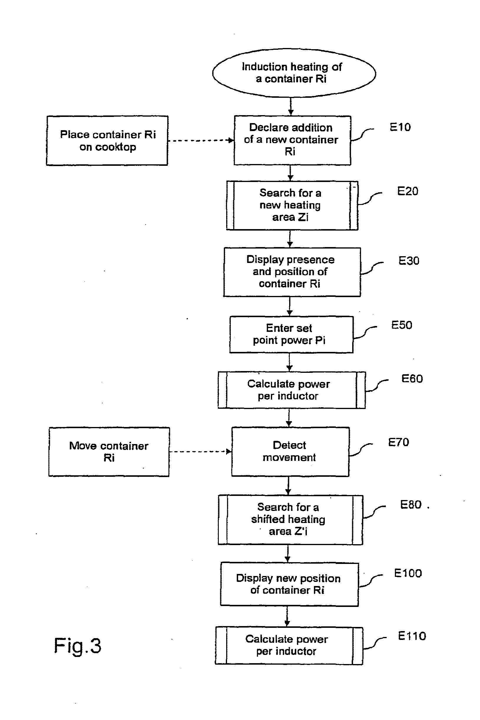
A method for heating a container (Ri) placed on a cooktop including heating elements which are associated respectively with inductors which form elements for detecting the presence of the container and are distributed along a frame which is embodied such that it is two-dimensional in a cooking area. The method includes searching (E20) a heating area (Zi) having the heating elements arrangement which are at least partially covered by the container and computing (E60) a power supplied by each heating element of the heating area (Zi) according to a total specified power (Pi) associated thereto and the degree of coverage of each detection element associated to heating element by the container (Ri). Utilization, in particular, is for an inductive cooktop.

Description

CROSS REFERENCE TO RELATED APPLICATIONS[0001]This application is a divisional of co-pending application Ser. No. 10 / 580,680 filed on Oct. 12, 2006, which is the 35 U.S.C. §371 national stage of International PCT / FR04 / 02905 filed on Nov. 12, 2004, which claims priority to French Application No. 0313925 filed on Nov. 27, 2003. The entire contents of each of the above-identified applications are hereby incorporated by reference.BACKGROUND OF THE INVENTION[0002]1. Field of the Invention[0003]The present invention relates to a method of heating a container placed on a cooktop[0004]It also relates to a cooktop adapted to implement the heating method of the invention.[0005]It relates generally to cooktops of the kind such that a container may be placed and heated anywhere on the cooking surface.[0006]It finds a particular, non-exclusive application in the field of induction cooktops.[0007]2. Description of the Related Art[0008]The document WO 97 37 515 discloses a cooktop in which a cookin...

Claims


Application Information

Patent Timeline
Patent Type & Authority Applications(United States)
IPC IPC(8): H05B6/12F24C7/08H05B6/06
CPCH05B6/065H05B2213/05H05B2213/03
Inventor GOUARDO, DIDIERGOUMY, CEDRICROUX, ALAIN
Owner GRP BRANDT
Learn More