
Adjustable tilt solar panel support system

a solar panel and support system technology, applied in the direction of machine supports, heat collector mounting/supports, light and heating equipment, etc., can solve the problems of inability to adjust, reduce the capacity of solar modules in fixed title systems, and affect the capture efficiency of solar modules

Inactive Publication Date: 2010-09-30
THOMPSON TECH IND
View PDF9 Cites 24 Cited by
  • Summary
  • Abstract
  • Description
  • Claims
  • Application Information

AI Technical Summary

Benefits of technology

[0021]Summarily, a principal object and advantage of the present invention is to provide a stationary solar panel mounting system with means to effect and easy, manual adjustment of a solar panel array to the Sun's southern exposure without the need for motorized apparatus.
[0022]The foregoing summary broadly sets out the more important features of the present invention so that the detailed description that follows may be better understood, and so that the present contributions to the art may be better appreciated. There are additional features of the invention that will be described in the detailed description of the preferred embodiments of the invention which will form the subject matter of the claims appended hereto.
[0023]Accordingly, before explaining the preferred embodiment of the disclosure in detail, it is to be understood that the disclosure is not limited in its application to the details of the construction and the arrangements set forth in the following description or illustrated in the drawings. The inventive apparatus described herein is capable of other embodiments and of being practiced and carried out in various ways.
[0024]As such, those skilled in the art will appreciate that the conception, upon which this disclosure is based may readily be used as a basis for designing other structures, methods, and systems for carrying out the several purposes of the present invention. It is important, therefore, that the claims are regarded as including such equivalent constructions as far as they do not depart from the spirit and scope of the present invention. Rather, the fundamental aspects of the invention, along with the various features and structures that characterize the invention, are pointed out with particularity in the claims annexed to and forming a part of this disclosure. For a better understanding of the present invention, its advantages and the specific objects attained by its uses, reference should be made to the accompanying drawings and descriptive matter in which there is illustrated the preferred embodiment and best mode of practicing the invention.

Problems solved by technology

Further, as the Sun's position changes during the year (or more accurately, as the angle between the Earth's axis and the Earth-Sun line changes throughout the year), the capture efficiency of a solar module in a fixed title system is significantly affected, at times adversely.
Although this method of support provides the necessary support structure for operation of a solar panel or panel array, there are a number of limitations.
It therefore cannot be adjusted for seasonal changes in the Sun's relative position, and this dramatically limits solar collection efficiency.
Therefore the design of the structure cannot be finalized until the construction site is precisely known.
Next, with few exceptions, the angular position of the structure requires that the modules be mounted in an unstable orientation, and this may cause additional assembly effort as well as increase the potential for damage to the modules.

Method used


Image

  • Adjustable tilt solar panel support system
  • Adjustable tilt solar panel support system
  • Adjustable tilt solar panel support system

Examples


Embodiment Construction

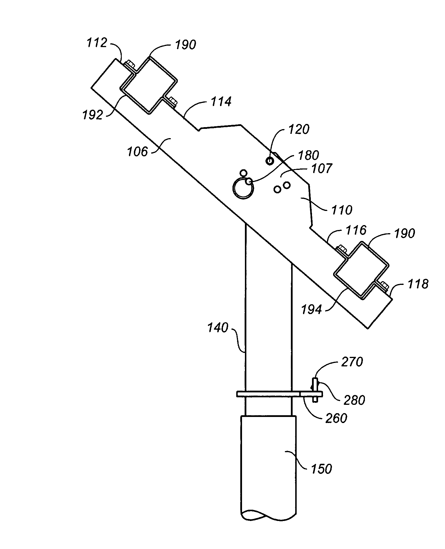
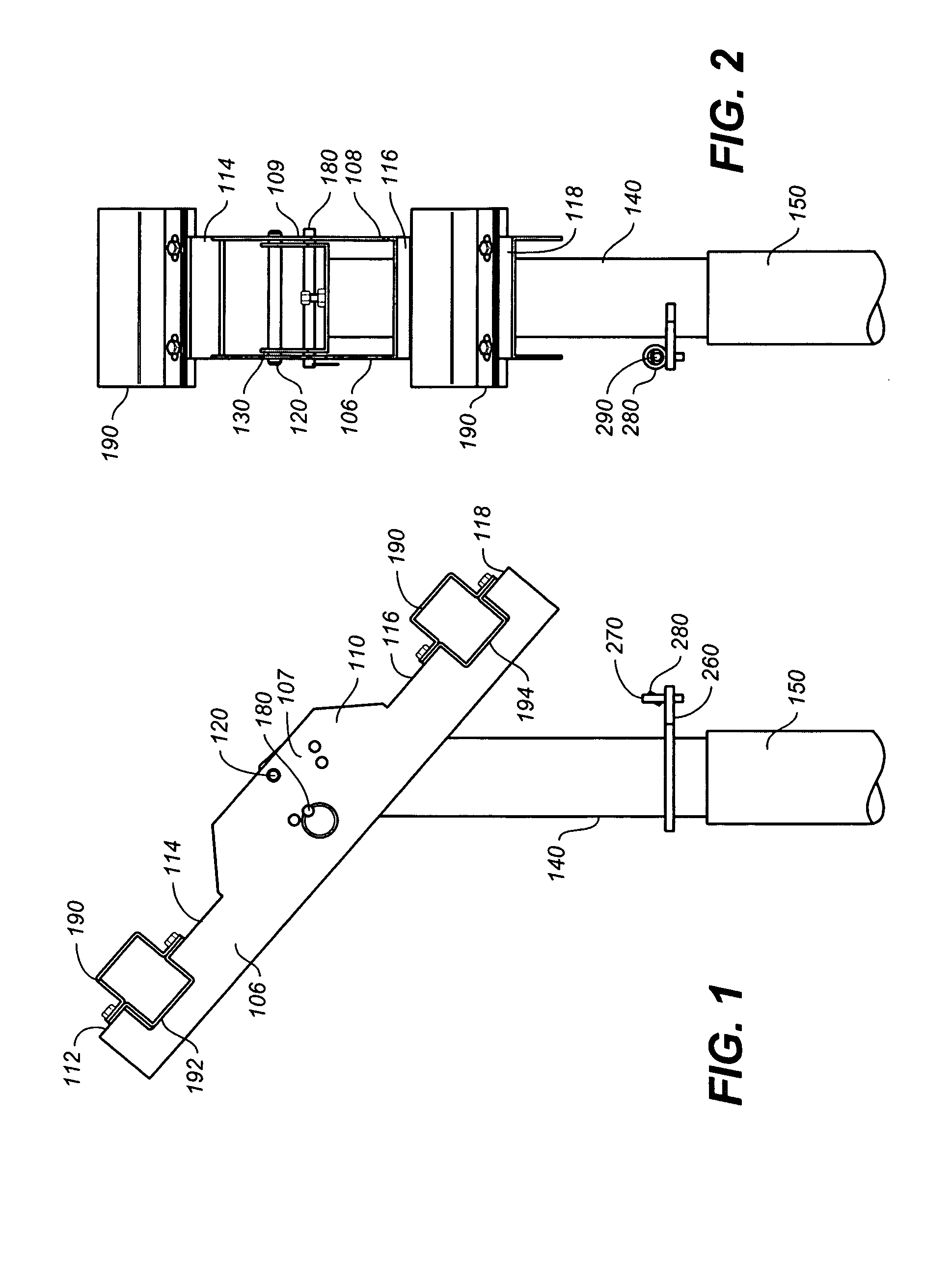
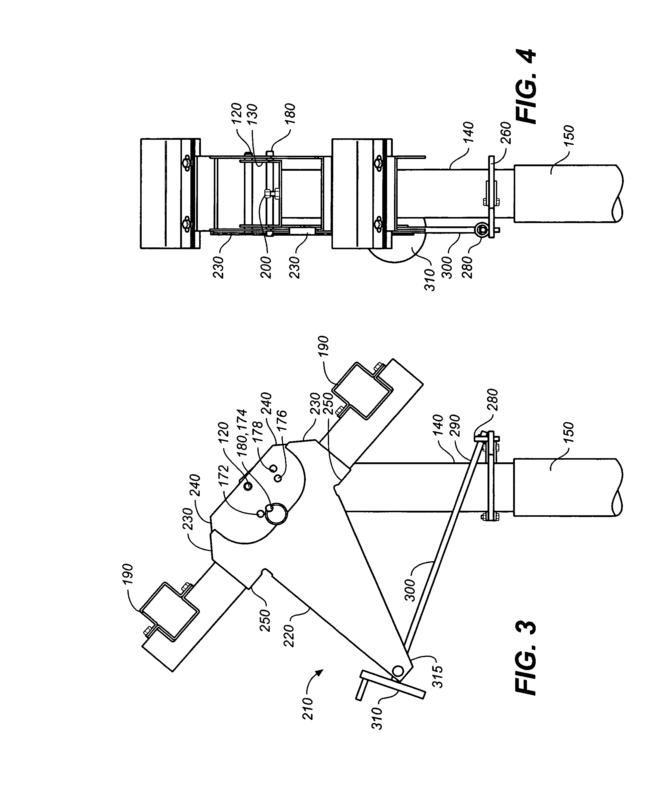
[0033]Referring to FIGS. 1 through 6, wherein like reference numerals refer to like components in the various views, there is illustrated therein a new and improved adjustable tilt solar panel support apparatus, generally denominated 100 herein.

[0034]The inventive apparatus includes a rotational support cradle 110, which is the primary rotational and adjustment element of the system. The rotational support cradle, in its most essential aspect, comprises substantially planar parallel elongate side bars 106, 108, joined by a plurality of cross bars 112, 114, 116, 118. Each side bar preferably includes an expanded medial portion 107, 109, so as to accommodate the adjustment features described below. Using a pivot pin 120 the rotational support cradle is mounted to a pivot bracket 130, which in turn is attached to a support post or cinch tube 140 adjustably inserted into, and secured in, a piling 150. The cinch tube includes either an expander or wedge at its lower end and either an ang...


PUM


Abstract

An adjustable tilt solar panel support system including a support post, a U-shaped pivot bracket attached to the support post in a generally upright orientation and having a pivot pin hole for accommodating a pivot pin, and further having at least one adjustment opening; a rotational support cradle having a pivot pin hole in alignment with the pivot pin hole of the pivot bracket, such that the support cradle is pivotally attached to the pivot bracket, the support cradle further including at least one adjustment opening which aligns with the adjustment opening of the pivot bracket. An adjustment pin is selectively inserted into and through the adjustment openings of the support cradle and pivot bracket to secure the support cradle at a selected angle, and wherein the removal of the adjustment pin permits the rotational support cradle to pivot on the pivot bracket about the pivot pin.

Description

BACKGROUND OF THE INVENTION[0001]1. Technical Field[0002]The present invention relates generally to solar panel photovoltaic systems, and more particularly to solar panel array installations, and still more particularly to an adjustable tiltable support apparatus for a solar panel module array.[0003]2. Background Art[0004]Numerous kinds of support apparatus for solar panels are well known. Indeed, the present inventors have contributed significantly to the field, including disclosure of a solar panel array sun tracking system that describes a support cradle employed in the present invention. That inventive system was disclosed International Patent Application Serial Number PCT / US06 / 38185, and it is incorporated by reference in its entirety herein.[0005]Known published documents in the prior art include U.S. Pat. No. 6,563,040, to Hayden et al., which describes a tracking system tilted in a fixed southerly orientation. The tilt is fixed and is rotated east to west to track the diurna...

Claims


Application Information

Patent Timeline
IPC IPC(8): F16M11/10
CPCF24J2/5232F24J2/5264H02S20/00Y02E10/50Y02E10/47F24S25/12F24S25/70H02S20/30
Inventor ZANTE, ANTHONY A.MULLINS, MONTYSTAGER, CRAIGTHOMPSON, DANIEL S.
Owner THOMPSON TECH IND
Learn More