Rotor of rotary electric machine and method of manufacturing the same

a technology of rotor and electric machine, which is applied in the direction of manufacturing stator/rotor body, magnetic circuit rotating parts, and shape/form/construction of magnetic circuits, etc., can solve the problems of large moment, peeling of magnets from the rotor core, and prone to fracture, and achieve stable magnet retention strength and bonding strength, high reliability of the rotor

Inactive Publication Date: 2010-09-30
MITSUBISHI ELECTRIC CORP
View PDF7 Cites 42 Cited by
  • Summary
  • Abstract
  • Description
  • Claims
  • Application Information

AI Technical Summary

Benefits of technology

[0009]The present invention has been made to solve the foregoing problem, and an object of the present invention is to obtain a high reliability rotor of a rotary electric machine and a method of manufacturing the same, both of which can easily ensure stable magnet retention strength and bonding strength.

Problems solved by technology

In the case of magnetization of permanent magnets and during product operation, a large external force is exerted on the magnets; however, if bonding strength of segment shaped magnets and a rotor core is biased in an axial direction, it is likely to fracture because a large moment is exerted on the magnets.
In addition, if a bonding state is bad, it causes that peel-off of the magnets from the rotor core occurs and a large moment is exerted on the magnets in the case of the magnetization and during the product operation as in the above mention.
However, the adhesive is formed on only the shaft end faces and / or circumferential end faces of the permanent magnets; and therefore, there is a case that it is not possible to obtain sufficient bonding strength.

Method used


Image

  • Rotor of rotary electric machine and method of manufacturing the same
  • Rotor of rotary electric machine and method of manufacturing the same
  • Rotor of rotary electric machine and method of manufacturing the same

Examples


embodiment 1

Preferred Embodiment 1

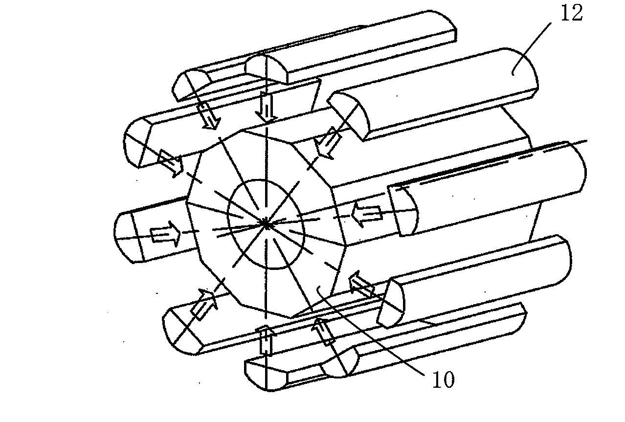
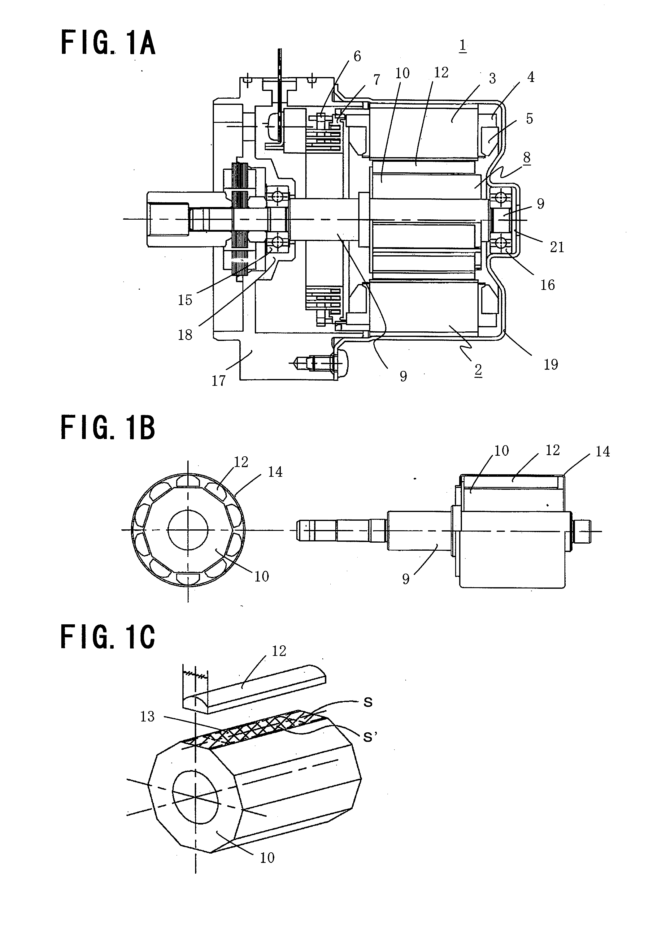
[0029]FIGS. 1A to 1C show a rotor of a rotary electric machine of Preferred Embodiment 1 of the present invention; FIG. 1A is a sectional view showing an example applicable to a motor for an electric power steering apparatus; FIG. 1B is a detail view of a rotor structure shown in FIG. 1A; and FIG. 1C is a view showing a bonded state between each of segment shaped magnets and a rotor core. In FIGS. 1A, 1B, and 1C, a rotary electric machine 1 is a permanent magnet rotary electric machine, and three phase stator windings 5 are wound via a resin-made insulator 4 on a stator core 3 formed by laminating magnetic steel sheets. Respective phase windings are connected in star or delta by winding terminals 6 placed in a resin-made terminal holder 7. The stator core 3 is fixed to an iron frame 19 by press-fitting and the like to constitute a stator 2 of the rotary electric machine 1. The frame 19 has a bottom face at one end portion thereof; and on the central portion of ...

embodiment 2

Preferred Embodiment 2

[0036]FIG. 2 is a detail view of a rotor structure of Preferred Embodiment 2 of the present invention, and is a view showing a relationship between a circumscribed circle diameter of an outer circumference of respective magnets and a ring inner diameter of a rotor.

[0037]That is, in the Preferred Embodiment 2, an inner diameter ΦDri of a ring 14 is set smaller than a circumscribed circle diameter ΦDm of an outer circumference of respective segment shaped magnets 12 bonded and fixed to an outer circumference face of a rotor core 10, and the segment shaped magnets 12 are biased to the radial direction side of the rotor core 10 in a state with an appropriate exposed thread.

[0038]According to the thus configured rotor of the rotary electric machine of Preferred Embodiment 2, a pull force is produced in a circumferential direction on the ring 14; however, by such an elastic force and an elastic force of an adhesive 13 intervened between each of the segment shaped mag...

embodiment 3

Preferred Embodiment 3

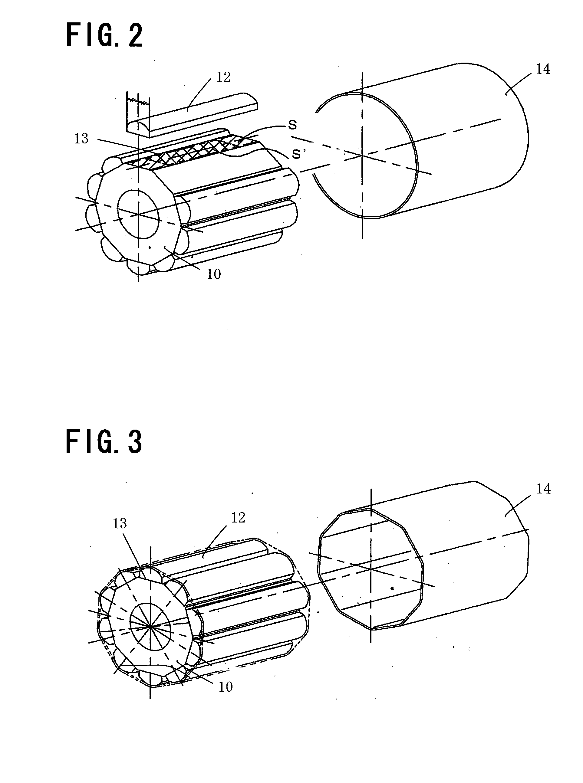
[0040]FIG. 3 is a detail view of a rotor structure of Preferred Embodiment 3 of the present invention, and is a view showing a shape of a ring attached to an outer diameter of rotor magnets.

[0041]That is, in Preferred Embodiment 3, a ring 14 is formed in a polygon shape along an outer circumference shape of respective segment shaped magnets 12.

[0042]According to the thus configured rotor of the rotary electric machine of Preferred Embodiment 3, since the shape of the ring 14 is a polygon shape along the outer circumference face of the respective segment shaped magnets 12, a circumferential biasing force can also be applied in addition to a radial biasing force. Therefore, there can be suppressed the occurrence of large stress against an external force applied to the segment shaped magnets 12 in the case of magnetization and during product operation; further, the segment shaped magnets 12 do not move in a circumferential direction during hardening of an adhesive...


PUM

PropertyMeasurementUnit
outer circumferenceaaaaaaaaaa
areaaaaaaaaaaa
shapeaaaaaaaaaa

Abstract

In a rotor of a permanent magnet rotary electric machine, a bonding portion between each of segment shaped magnets and an outer circumference face of a rotor core is provided in axial symmetry with respect to the rotor axial center and has a bonding area equal to or larger than a half of a contact area between each of the segment shaped magnets and the outer circumference face of the rotor core; and a biasing force is applied to an outer circumference face of the segment shaped magnets by a ring.

Description

BACKGROUND OF THE INVENTION[0001]1. Field of the Invention[0002]The present invention relates to rotors of rotary electric machines and, more particularly, relates to a structure of a rotor of a permanent magnet rotary electric machine and a method of manufacturing the same.[0003]2. Description of the Related Art[0004]As known rotors of rotary electric machines, there is known one in which an adhesive is formed on shaft end faces and / or circumferential end faces of permanent magnets in order to prevent a crack in the magnets in the case of magnetization of the permanent magnets.[0005](For example, see Japanese Unexamined Patent Publication No. 2005-65388)[0006]In the case of magnetization of permanent magnets and during product operation, a large external force is exerted on the magnets; however, if bonding strength of segment shaped magnets and a rotor core is biased in an axial direction, it is likely to fracture because a large moment is exerted on the magnets. In addition, if a ...

Claims


Application Information

Patent Timeline
Patent Type & Authority Applications(United States)
IPC IPC(8): H02K1/28H02K15/03
CPCY10T29/49012H02K1/278H02K1/2781
Inventor FUJIMOTO, KENGOASAO, YOSHIHITOAKUTSU, SATORUTAKASHIMA, KAZUHISA
Owner MITSUBISHI ELECTRIC CORP
Why Eureka
Try Eureka