This helps you quickly interpret patents by identifying the three key elements:
Problems solved by technology
Method used
Benefits of technology
[0011]Accordingly, it is an aspect of the present invention to provide an inkjet print head that, while being suitable to use with electrically conduc
Problems solved by technology
However, in this method of first providing joined plates of a ceramic piezoelectric plate in which electrodes and the protection films are deposited within the groves and the ink chamber plate covering the grooves to form the ink chambers, adherin
Method used
Image
Click on the blue label to locate the original text in one second.
Reading with bidirectional positioning of images and text.
Examples
embodiment 1
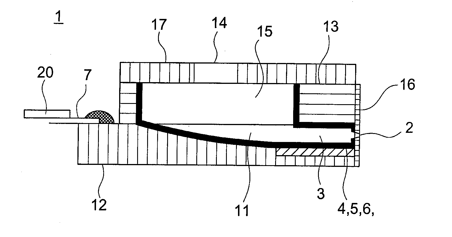
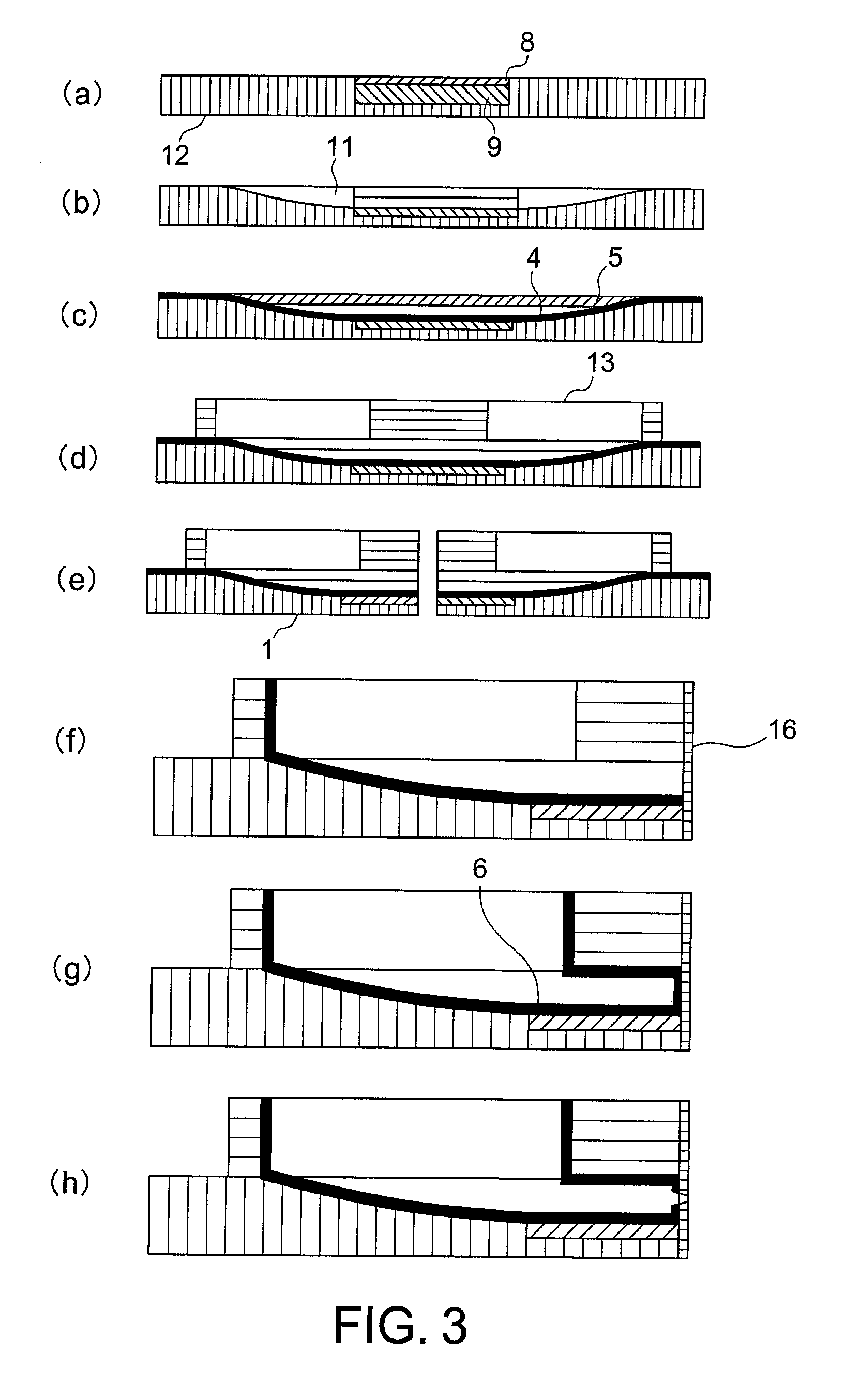
[0036]Shown in FIG. 3 are cross-section views illustrating the process of fabricating inkjet print head 1 in the first embodiment. FIGS. 3(a) to 3 (h) show the sequence of the fabrication process.
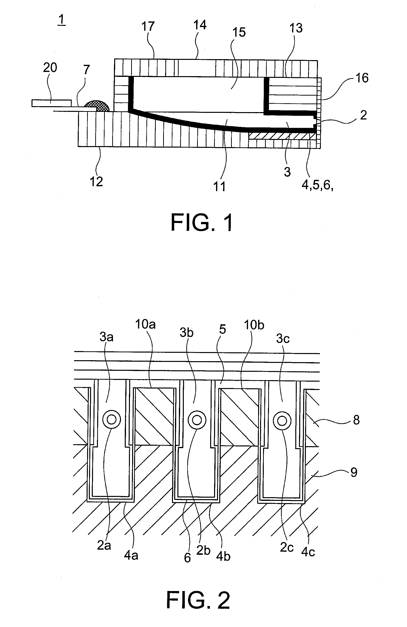
[0037]FIG. 3 (a) shows a preparation stage of substrate 12. Two piezoelectric members (PZT) 8, 9, which are polarized so that the respective polarization directions oppose each other, are adhered together, and the joined members are embedded into substrate 12 and adhered to it. For substrate 12, a PZT having a lower dielectric constant than those of piezoelectric members (PZT) 8, 9, as described earlier, is used.
[0038]FIG. 3 (b) shows a process of forming longi-groove 11. Substrate 12 prepared as shown in FIG. 3 (a) is grooved by cutting work by a diamond cutter so as to form multiple grooves 11 in parallel with the end surface of substrate 12 traversing piezoelectric members (PZT) 8, 9 in a constant interval. The width of the longi-groove became 80 μm due to the use of a diamond cutter hav...
second embodiment
[0067]Now, a description will be made for the second embodiment.
[0068]FIG. 7(a) shows a process of preparing substrate 12. Two piezoelectric members (PZT) 8, 9, which are polarized so that the respective polarization directions oppose each other, are adhered together, and the adhered members are embedded into substrate 12. As described earlier, substrate 12 uses a PZT having a lower dielectric constant than those of piezoelectric members (PZT) 8, 9.
[0069]FIG. 7(b) shows a process of forming longi-groove 11. Multiple longi-grooves 11 having a certain interval are formed by cutting work by a diamond cutter in parallel with the end surface of substrate 12 traversing piezoelectric members (PZT) 8, 9.
[0070]FIG. 7(c) shows a process of forming electrode 4, first protecting film 5, and second protecting film 6. An electrode pattern is formed on the surface of a substrate and internal surface of longi-groove 11 by means of the electroless nickel plating, and then the Au plating is applied o...
PUM
Property
Measurement
Unit
Thickness
aaaaa
aaaaa
Length
aaaaa
aaaaa
Pressure
aaaaa
aaaaa
Abstract
An inkjet print head is fabricated by, fist, forming an electrode and two layers of a protection film composed of an inorganic insulating film and an organic insulating film over the electrode within a groove of a piezoelectric member, adhering a top board to the piezoelectric member covering the groove to form a pressure chamber, adhering a polyimide plate so as to cover the groove, and then forming a nozzle in the polyimide plate by the excimer laser processing aligning to the pressure chamber. Herein, the excimer laser light penetrates the polyimide plate to form a nozzle, and further proceeds to be emitted on the organic insulating film. Consequently, the part of the organic insulating film irradiated by the laser light is damaged. To prevent the damage of the organic insulating film, the thickness of the inorganic insulating film in the part to which the excimer laser light is emitted is prepared to be 0.5 μm or more.
Description
CROSS REFERENCE TO RELATED APPLICATION[0001]This application is based upon and claims the benefit of priority from the prior Japanese Patent Applications No. 2009-10602 filed on Jan. 21, 2009 and No. 2009-148355 filed on Jun. 23, 2009, the contents of which are incorporated herein by reference.BACKGROUND OF THE INVENTION[0002]1. Field of the Invention[0003]The present invention relates to an inkjet print head forming an image by ejecting ink droplets and a method of manufacturing the inkjet print head. The invention particularly relates to an inkjet head having an insulating film within a pressure chamber from which an ink droplet is ejected.[0004]2. Description of the Related Art[0005]JP laid-open application publication No. 2002-160364 describes a so-called shear-mode inkjet print head that ejects an ink droplet from a nozzle using shear-mode deformation of a piezoelectric material. FIG. 8 is a sectional view of an inkjet print head of this type.[0006]This publication describes a ...
Claims
Application Information
Patent Timeline
Application Date:The date an application was filed.
Publication Date:The date a patent or application was officially published.
First Publication Date:The earliest publication date of a patent with the same application number.
Issue Date:Publication date of the patent grant document.
PCT Entry Date:The Entry date of PCT National Phase.
Estimated Expiry Date:The statutory expiry date of a patent right according to the Patent Law, and it is the longest term of protection that the patent right can achieve without the termination of the patent right due to other reasons(Term extension factor has been taken into account ).
Invalid Date:Actual expiry date is based on effective date or publication date of legal transaction data of invalid patent.