Automatic tracking method and surveying device

a tracking method and technology of a surveying device, applied in the field of automatic tracking and a surveying device, can solve the problems of reducing the efficiency of measuring operation, the detection range of the reflection light for automatic tracking is too small, and the interruption of automatic tracking, so as to improve the accuracy of tracking the target, prevent erroneous measurement, and improve the effect of tracking the targ

Active Publication Date: 2010-09-30
KK TOPCON
View PDF27 Cites 37 Cited by
  • Summary
  • Abstract
  • Description
  • Claims
  • Application Information

AI Technical Summary

Benefits of technology

[0027]Further, the present invention provides the automatic tracking method as described above, comprising a step of taking a moving image of a target supported on a moving object and of the moving object, a target tracking step of tracking on the target based on the moving image, a moving object tracking step of tracking on the moving object based on the moving image, a step tracking comparing of comparing a target position obtained from the target tracking step with a position of the moving object obtained from the moving object tracking step, and a step of performing tracking based on a result of the tracking in case where the target position and the moving object position are within a predetermined range. As a result, it is possible to improve the accuracy of tracking of the target, and to prevent erroneous measurement due to incorrect recognition of the target.
[0028]Also, the present invention provides a surveying device, comprising a first image pickup unit for receiving and detecting a reflection light from a target supported by a moving object, a moving image pickup unit for taking moving images of the target and the moving object, a drive unit for shifting collimating direction of the first image pickup unit and the moving image pickup unit to horizontal direction and vertical direction, a light spot detection processing unit for detecting a light spot based on the image from the first image pickup unit, an image tracking processing unit for performing image processing for image tracking based on a picked-up image of the moving image pickup unit, a control arithmetic unit for controlling the drive unit so that the first image pickup unit and the moving image pickup unit are directed toward the target based on the result of processing of the light spot detection processing unit and of the image tracking processing unit, wherein the control arithmetic unit controls the drive unit so that tracking is performed based on the result of detection from the light spot detection processing unit, and so that the image tracking is performed in parallel to the tracking based on the result of processing from the image tracking processing unit. As a result, it is possible to improve the accuracy of tracking of the target, and to prevent erroneous measurement due to incorrect recognition of the target.
[0029]Further, the present invention provides the surveying device as described above, wherein the control arithmetic unit controls the drive unit so that searching is performed by a laser beam over a predetermined range based on an image position obtained by the image tracking and so that the target is detected in case where the light spot position obtained by the laser tracking and the image position obtained by the image tracking are not within a predetermined range or in case where the light spot position cannot be obtained. As a result, it is possible to detect the target promptly and to restore the tracking operation quickly because it is enough to search the vicinity of the image position obtained by image tracking in case where a plurality of light spots are detected or even in case where optical path of the laser beam is interrupted and the light spot cannot be detected.
[0030]Also, the present invention provides the surveying device as described above, wherein the control arithmetic unit extracts a moving object image from an image of the moving image pickup unit, generates a histogram from the moving object image, and identifies the moving object based on the histogram. As a result, even in case where the posture of the moving object is changed or even in case where a part of the moving object is interrupted by an obstacle, it is possible to perform image tracking.
[0031]Further, the present invention provides the surveying device as described above, wherein the control arithmetic unit judges velocity and moving direction of the moving object based on distance measurement data and angle measurement data and controls generation of particles according to the movement of the moving object. As a result, even in case where the posture of the moving object is changed or even in case where a part of the moving object is interrupted by an obstacle, it is possible to perform image tracking.
[0032]Also, the present invention provides the surveying device as described above, comprising a first image pickup unit for taking a moving image of a target supported on a moving object, a moving image pickup unit for taking moving images of the target and the moving object, a drive unit for shifting collimating direction of the first image pickup unit and the moving image pickup unit to horizontal direction and to vertical direction, a target tracking image processing unit for performing tracking of the target based on an image from the first image pickup unit, a moving object image tracking processing unit for performing tracking on the moving object based on the moving image, and a control arithmetic unit for controlling the drive unit so that the first image pickup unit the moving image pickup unit are directed toward the target based on a result of processing of the target tracking image processing unit and the moving object image processing unit, wherein the control arithmetic unit controls the drive unit so that tracking of the target is carried out based on a result of detection from the target tracking image processing unit, and so that the tracking on the moving object is carried out in parallel to the target tracking based on a result of processing from the moving object image tracking processing unit. As a result, the accuracy of the tracking of the target can be improved and erroneous measurement due to incorrect recognition of the target can be prevented. Further, even in case where the target is missed out of sight, it is possible to continue the tracking operation, to search the target quickly, and to easily restore the normal target tracking operation.

Problems solved by technology

In these cases, the surveying device may miss the target out of sight or may recognize the target by error and cannot track the target, and automatic tracking may be interrupted.
Such conditions are caused from the situations that, in case of general type of the collimating telescope, the field angle (view angle) is as small as about 1° and that detection range of the reflection light for automatic tracking is too small.
Further, under the working conditions where the optical path is frequently interrupted by obstacles, the problems may arise that the efficiency of the measuring operation is extremely decreased.

Method used


Image

  • Automatic tracking method and surveying device
  • Automatic tracking method and surveying device
  • Automatic tracking method and surveying device

Examples


Embodiment Construction

[0042]Referring to the attached drawings, description will be given below on an embodiment of the present invention.

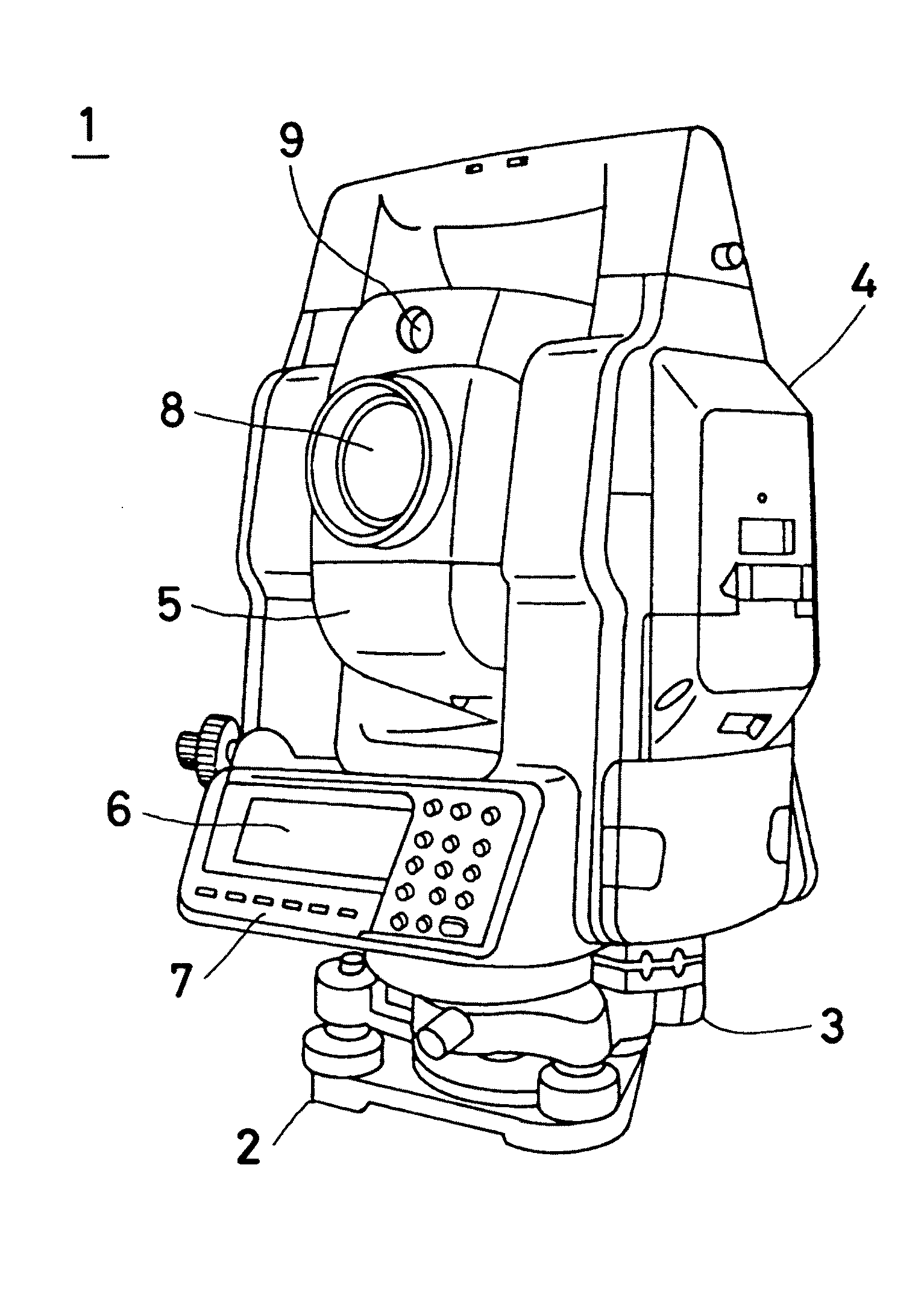
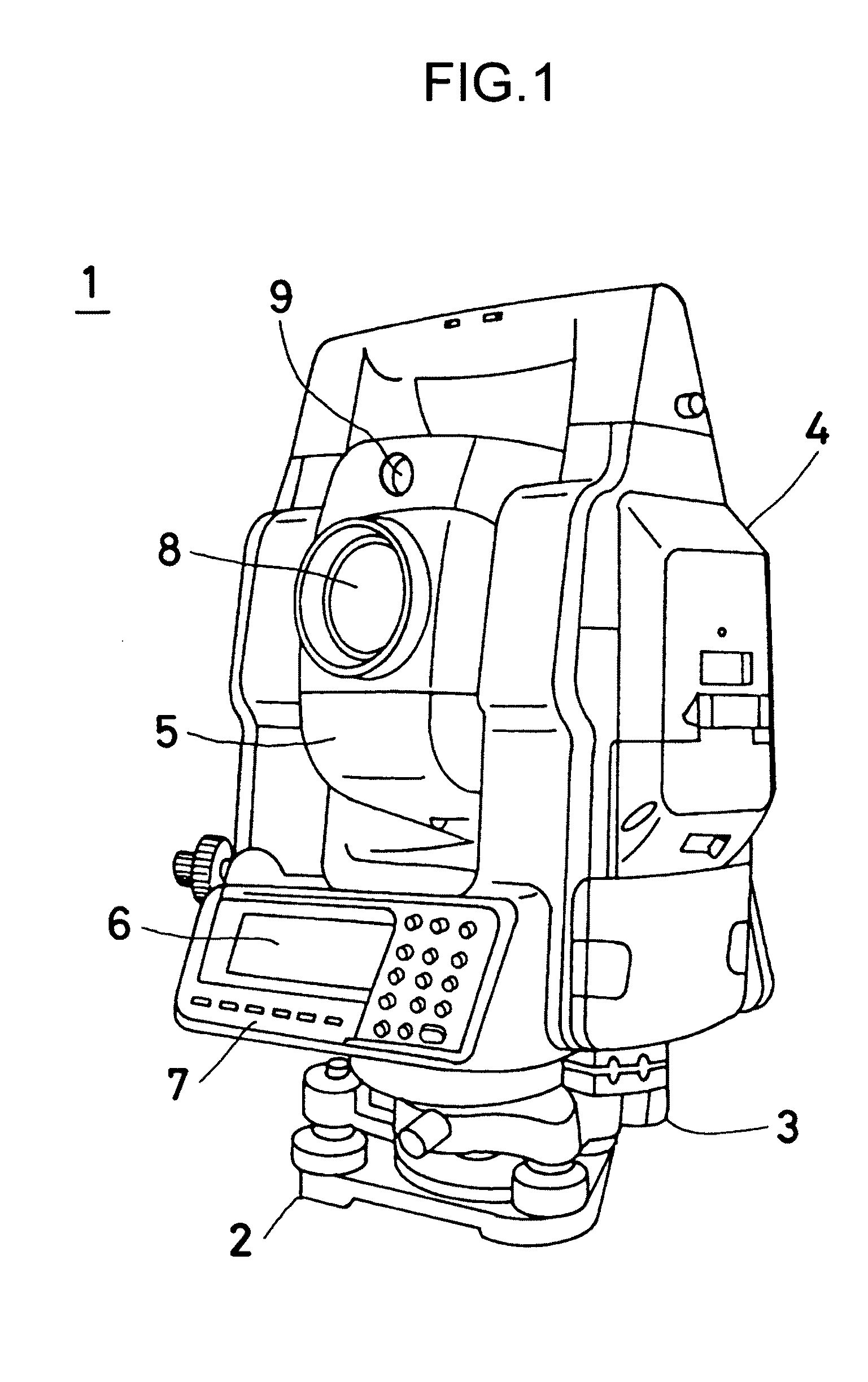
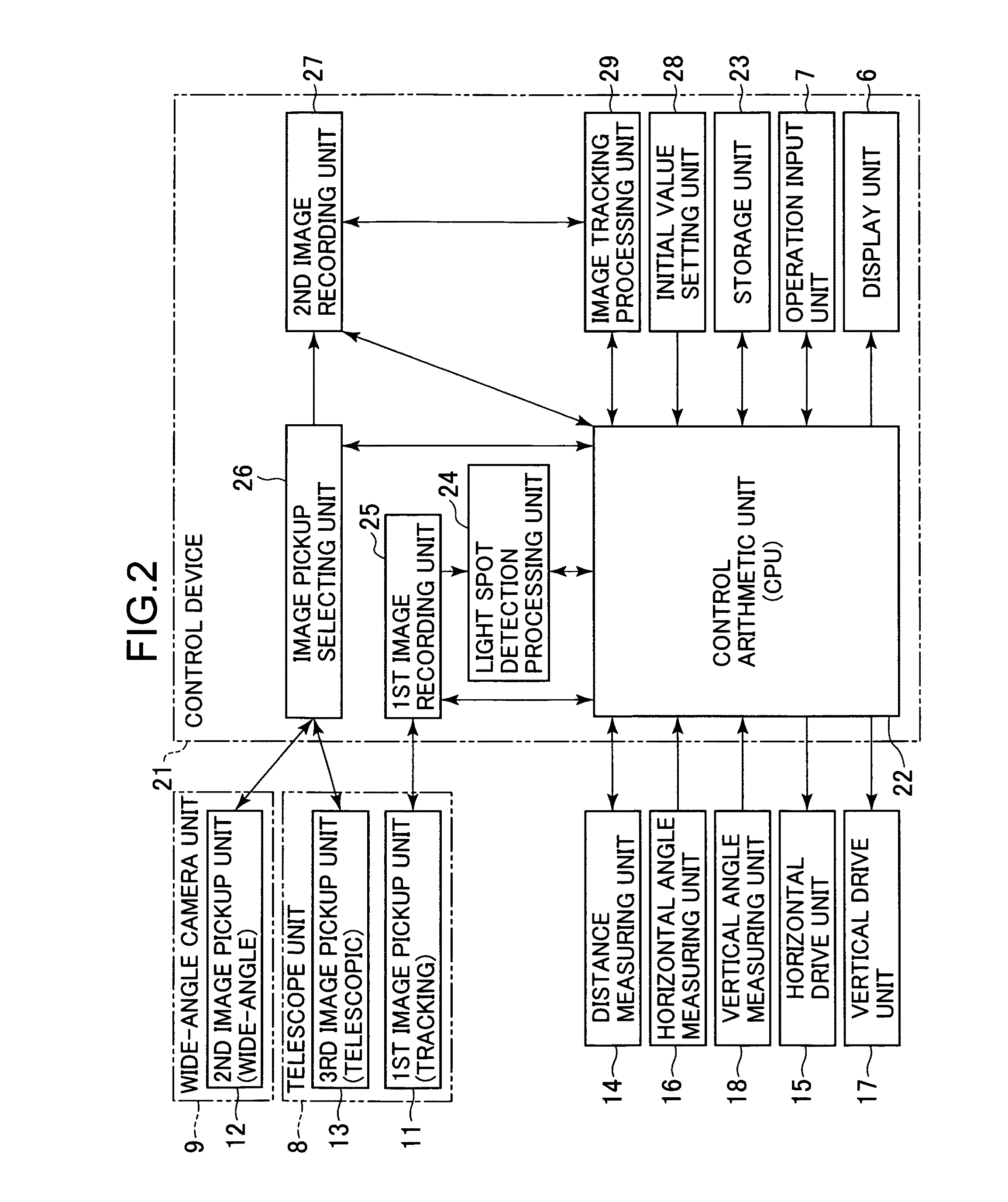
[0043]FIG. 1 and FIG. 2 each represents a surveying device 1, in which the present invention is carried out. The surveying device 1 as described here is a total station, for instance. The surveying device 1 projects a pulsed laser beam to a measuring point, receives a pulsed beam reflected from the measuring point, measures a distance for each pulse, averages the results of the distance measurements and carries out distance measurements with high accuracy.

[0044]As shown in FIG. 1, the surveying device 1 primarily comprises a leveling unit 2 mounted on a tripod (not shown), a base unit 3 provided on the leveling unit 2, a frame unit 4 rotatably disposed around a vertical axis on the base unit 3, and an optical unit 5 rotatably disposed around a horizontal axis on the frame unit 4.

[0045]The frame unit 4 comprises a display unit 6 and an operation input unit 7. The optica...


PUM


Abstract

The present invention provides an automatic tracking method, comprising a light spot detecting step of detecting a light spot 37 from a target 31 supported on a moving object 30, a step of taking a moving image of the target and the moving object, a step of tracking based on the detection of the light spot, a step of performing image tracking based on the moving image in parallel to the tracking, a step of comparing a position of the target obtained by the tracking with a position of the image obtained by the image tracking, and a step of tracking based on a result of the tracking in case where the target position and the image position are within a predetermined range.

Description

BACKGROUND OF THE INVENTION[0001]The present invention relates to an automatic tracking method and a surveying device having tracking function.[0002]As a surveying device for performing measurement of a distance, a horizontal angle, and a vertical angle, a surveying device having tracking function has been known in the past. In this type of surveying device, the surveying device collimates an object reflector (a target) such as a corner cube via a collimating telescope provided on the surveying device, and projects a tracking light via the collimating telescope. Then, the surveying device receives and detects a reflection light from the target via the collimating telescope and when the target moves, detects a deviation between a photodetecting position of the reflection light (from the target) and a collimation center. Based on the deviation, the surveying device adjusts the collimating direction and tracks the target automatically.[0003]Normally, in a surveying device having the tr...

Claims


Application Information

Patent Timeline
Patent Type & Authority Applications(United States)
IPC IPC(8): H04N5/225G06K9/00
CPCG01C15/002G01S17/023G06T2207/10016G06T7/204G06T7/208G01S17/66G06T7/248G06T7/277G01S17/86
Inventor OTANI, HITOSHIKOMEICHI, TAKAHIROIKOMA, NORIKAZUKAWAMOTO, KAZUHIKO
Owner KK TOPCON
Why Eureka
Try Eureka