Projector
a projector and projector technology, applied in the field of projectors, can solve the problems of light leakage, leakage of the light component, etc., and achieve the effect of suppressing the decrease in the contrast of the projected imag
- Summary
- Abstract
- Description
- Claims
- Application Information
AI Technical Summary
Benefits of technology
Problems solved by technology
Method used
Image

Examples
first embodiment
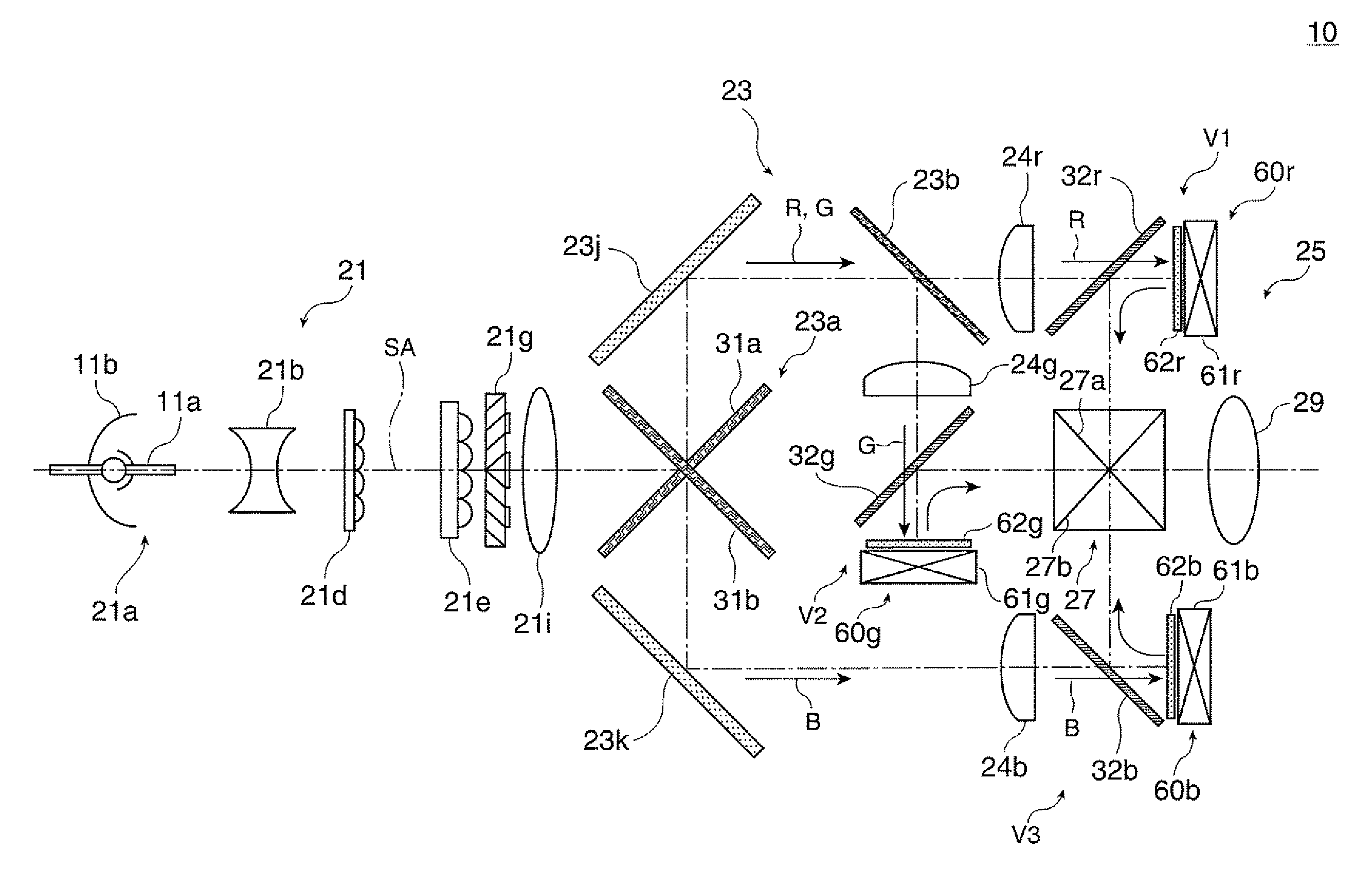
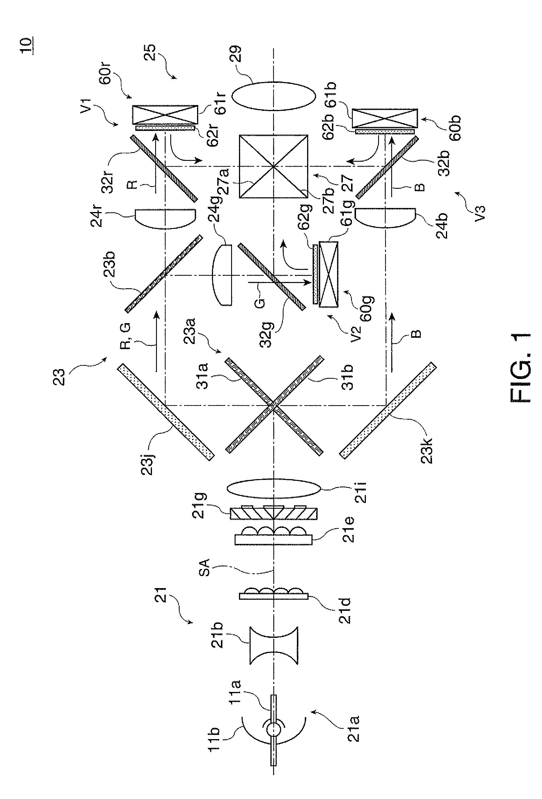
[0028]FIG. 1 is a conceptual plan view describing the configuration of the optical system of a projector according to a first embodiment of the invention.
[0029]The projector 10 includes a light source system that emits light-source light, a color separation / light guiding system 23 that separates the light-source light outputted from the light source system into red, green, and blue (RGB) three color light beams, a light modulating section 25 illuminated with the color light-source light beams having passed through the color separation / light guiding system 23, a cross dichroic prism 27 that combines the color image light beams outputted from the light modulating section 25, and a projection lens 29, which is a projection system that projects the image light having passed through the cross dichroic prism 27 on a screen (not shown). Among the components described above, the light source system 21, the color separation / light guiding system 23, the light modulating section 25, and the cr...
second embodiment
[0049]FIGS. 6A and 6B are a plan view and a side view, respectively, conceptually describing the configuration of an optical compensator used in a projector according to a second embodiment. In the projector according to the present embodiment, an optical compensator 362g absorbs the polarized unwanted light LL so that no leakage light or stray light is produced from the unwanted light LL and hence the unwanted light LL does not cause decrease in contrast of a projected image. The example shown in FIGS. 6A and 6B describes a variation of the projector 10 shown, for example, in FIG. 1, and portions that will not particularly be described are the same as those in the first embodiment.
[0050]In the present embodiment, the optical compensator 362g includes the optical compensation element 63 and a compensator frame 364. The compensator frame 364 includes the frame body 64a and organic polarization members 364b, 364c, 364d, and 364e. Each of the organic polarization members 364b to 364e, ...
third embodiment
[0052]FIG. 7A is an enlarged partial side view conceptually describing the configuration of an optical compensator used in a projector according to a third embodiment. The example shown in FIG. 7A describes a variation of the projector 10 shown, for example, in FIG. 1, and portions that will not particularly be described are the same as those in the first embodiment.
[0053]In the present embodiment, an optical compensator 462g includes not only the reflector 64c, which is a typical polarization maintaining reflector, but also a second reflector 463d on an optical compensation element 463. The second reflector 463d functions as an auxiliary polarization maintaining reflector. In the optical compensator 462g, the optical compensation element 463 is bonded to the compensator frame 64 with an adhesive GL, such as a double-sided adhesive tape, placed continuously or intermittently at the periphery of the optical compensation element 463. When unwanted light is incident on the adhesive GL,...
PUM
 Abstract
Description
Claims
Application Information