
Multispectral Imaging Device with MOEMS Type Filter for Satellite Observation

a multi-spectral imaging and satellite observation technology, applied in the direction of optical radiation measurement, instruments, spectrometry/spectrophotometry/monochromators, etc., can solve the problem of difficult manufacture of filters

Inactive Publication Date: 2010-09-30
THALES SA
View PDF7 Cites 18 Cited by
  • Summary
  • Abstract
  • Description
  • Claims
  • Application Information

AI Technical Summary

Benefits of technology

[0005]In order notably to resolve this problem of excessive distance, the present invention proposes a multispectral imaging device comprising a unique structure that can be controlled electrically so as to produce a filtering function in a chosen wavelength band, and thus no longer using the conventional stacks of layers. The benefit of the invention also lies in the possibility of varying the spectral filtering function in wavelength and spectral width.
[0009]a set of N rows of detectors making it possible to acquire images of said observed area;
[0011]a first dispersion element (R1,R) making it possible to disperse the light beam toward the filtering means;
[0013]control means for said micro-opto-electro-mechanical system making it possible to select the filtering function;
[0014]a second dispersion element (R2) making it possible to recombine all the filtered beams at the output of the filtering means.
[0018]According to a variant of the invention, the device also comprises a second dispersive element that makes it possible to recombine all the filtered beams at the output of the filtering means.

Problems solved by technology

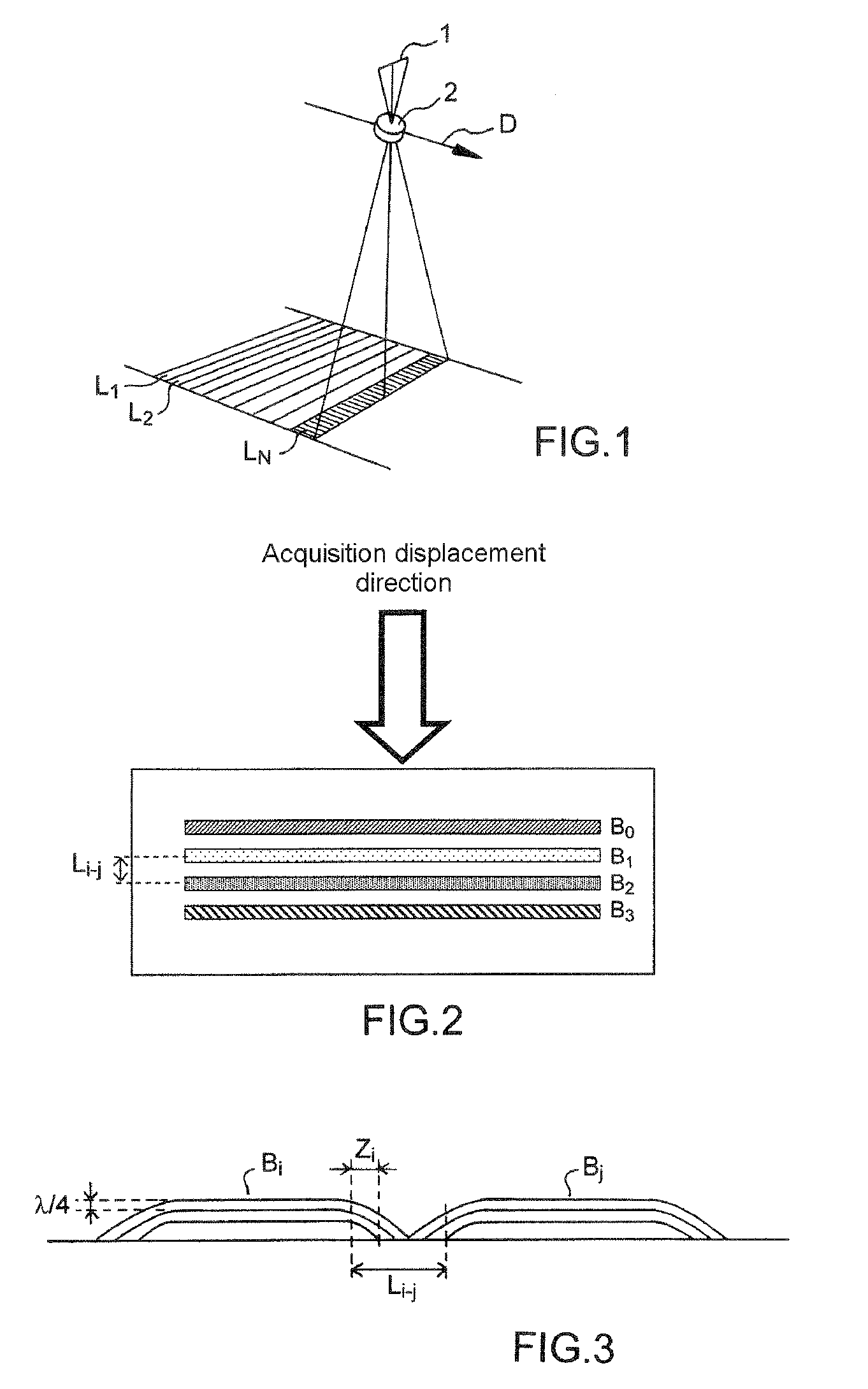
These filters are difficult to manufacture because they are made up of stacks of thin layers on the surface of a substrate. FIG. 3 shows an example of layer stacking, typically around 20 layers distributed over both faces of a substrate may be necessary to form a filter in a given wavelength range.
The second drawback is associated with the fact that the various filters are produced in a connected way on one and the same substrate as illustrated in FIG. 3 that diagrammatically represents the production of two types of stacking that make it possible to provide filtering functions in wavelength bands Bi and Bj.

Method used


Image

  • Multispectral Imaging Device with MOEMS Type Filter for Satellite Observation
  • Multispectral Imaging Device with MOEMS Type Filter for Satellite Observation
  • Multispectral Imaging Device with MOEMS Type Filter for Satellite Observation

Examples


Embodiment Construction

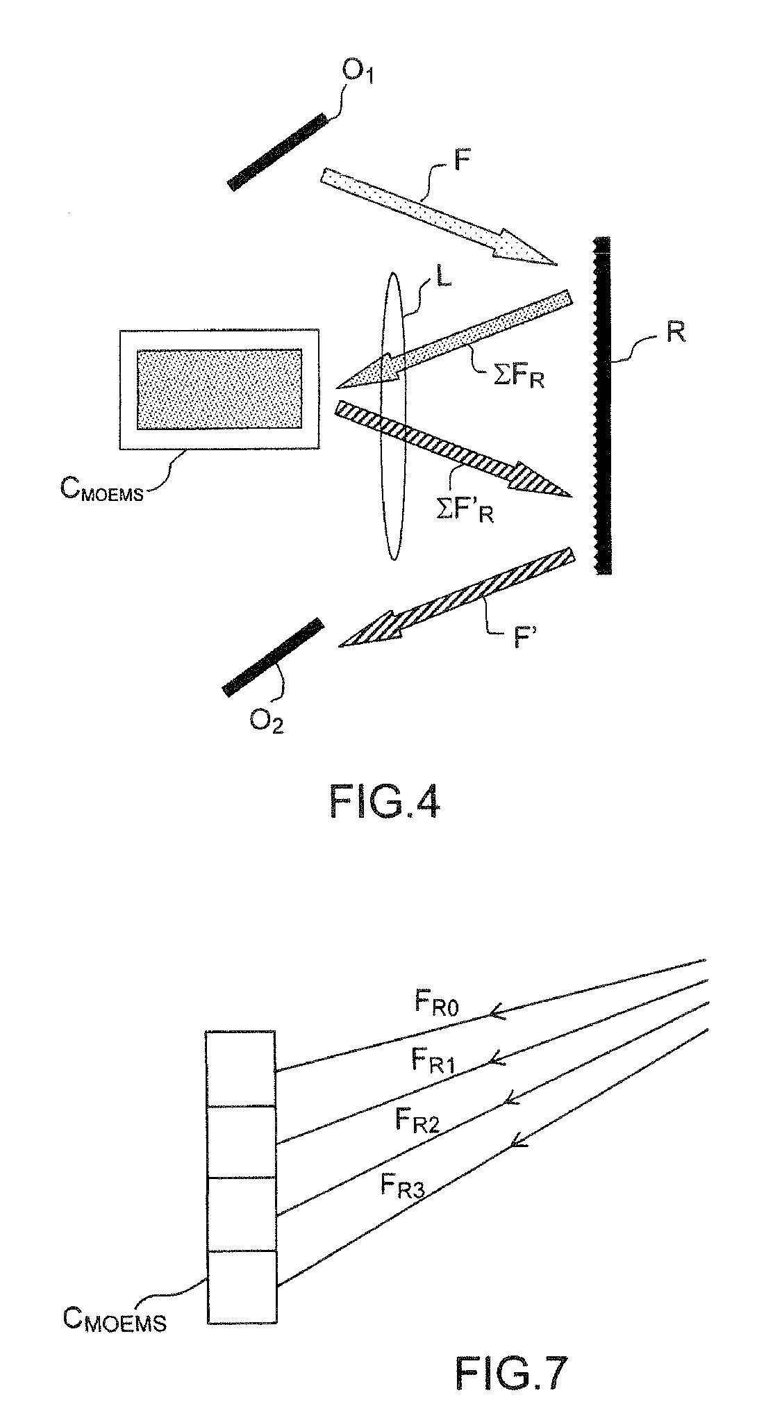
[0036]Generally, the inventive device comprises wavelength filtering means to produce different colored beams so as to carry out multispectral imaging comprising an MOEMS (micro-opto-electro-mechanical system) type component, simultaneously offering mechanical, electrical and optical functions. This type of component, when judiciously associated with a dispersive element in a multispectral imaging device, makes it possible to produce a number of filtering functions in different wavelength bands using an electrical control. The spectral adjustment can be ultrafast thanks to the high speed of the MOEMS components as will be explained hereinbelow.

[0037]In a first exemplary embodiment of the invention, the device can comprise a single diffraction array on the incident path at the level of the MOEMS component and of the reflected path. Thus, according to one example of this type of configuration, illustrated in FIG. 4, the device comprises a wide field optic 01 directing a beam F of poly...


PUM


Abstract

The invention relates to a multispectral imaging device for satellite observation by “push-broom” scanning over an observed area, operating in N wavelength bands, respectively centered on a first wavelength (λ1), . . . , an nth wavelength (λN) comprising:a source emitting a light beam in a set of the N wavelength bands;a wide-field optic;a set of N rows of detectors making it possible to acquire images of said observed area;optical filtering means,characterized in that it also comprises:a first dispersion element (R1,R) making it possible to disperse the light beam toward the filtering means;optical filtering means comprising at least one micro-opto-electro-mechanical system (MOEMS) capable of carrying out N filtering functions for the N spectral bands, wavelength-tunable;control means for said micro-opto-electro-mechanical system making it possible to select the filtering function.

Description

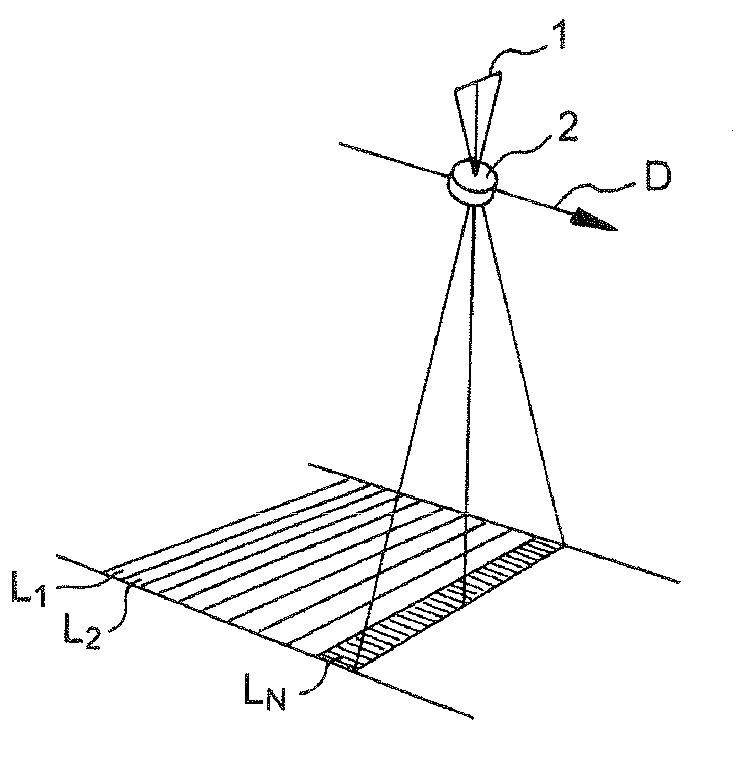
PRIORITY CLAIM[0001]This application claims priority to PCT Patent Application Number PCT / EP2008 / 005424, entitled Multispectral Imaging Device With MOEMS Type Filter For Satellite Observation, filed Jul. 3, 2008.FIELD OF THE INVENTION[0002]The invention relates to a multispectral observation device used notably for the acquisition of satellite observation images of the ground by “push-broom” scanning from strips of detectors of the charge-coupled type (CCD) for example, scrolling facing the observed area.BACKGROUND OF THE INVENTION[0003]The push-broom principle is illustrated in FIG. 1 diagrammatically in the case of a strip of detectors 1. This strip on board the satellite carries out the successive observation, as the satellite moves, of rows L1, L2, . . . , LN perpendicular to the direction of displacement D. A wide field optic 2 forms the image of the ground on a row of detectors located in the focal plane. The row scan is obtained by reading the sensitive elements of the detect...

Claims


Application Information

Patent Timeline
IPC IPC(8): G01J3/28
CPCG01J3/02G01J3/021G01J2003/1213G01J3/06G01J3/2823G01J3/0229
Inventor VIARD, THIERRYZAMKOTSIAN, FREDERIC
Owner THALES SA
Learn More