Method for orienting a parallax barrier screen on a display screen

a technology of parallax and display screen, which is applied in the direction of instruments, measurement devices, electrical appliances, etc., can solve the problems of reducing the brightness of this type of 3-d system in comparison with a 2-d display, the failure of wide-scale dissemination of autostereoscopic systems for a long time, and the reduction of the brightness of this type of 3-d systems in a short time. , to achieve the effect of precise orientation and large viewing distan

Inactive Publication Date: 2010-09-30
WISE VISION HLDG
View PDF9 Cites 28 Cited by
  • Summary
  • Abstract
  • Description
  • Claims
  • Application Information

AI Technical Summary

Benefits of technology

[0012]It is therefore an object of the invention to provide a way for orienting a parallax barrier screen on a display screen to generate a display screen for three-dimensional representation with the simplest means possible, so that a sufficiently precise

Problems solved by technology

A widespread dissemination of autostereoscopic systems did not succeed for a long time, however.
A disadvantage here, as in all barrier methods, is the high light loss.
A disadvantage here as well, however, is the greatly reduced brightness of this type of 3-D systems in comparison with a 2-D display.
The embodiments and teaching disclosed in this publication, however, usually produce unpleasant moiré effects and/or a greatly limited dep

Method used


Image

  • Method for orienting a parallax barrier screen on a display screen
  • Method for orienting a parallax barrier screen on a display screen
  • Method for orienting a parallax barrier screen on a display screen

Examples


Embodiment Construction

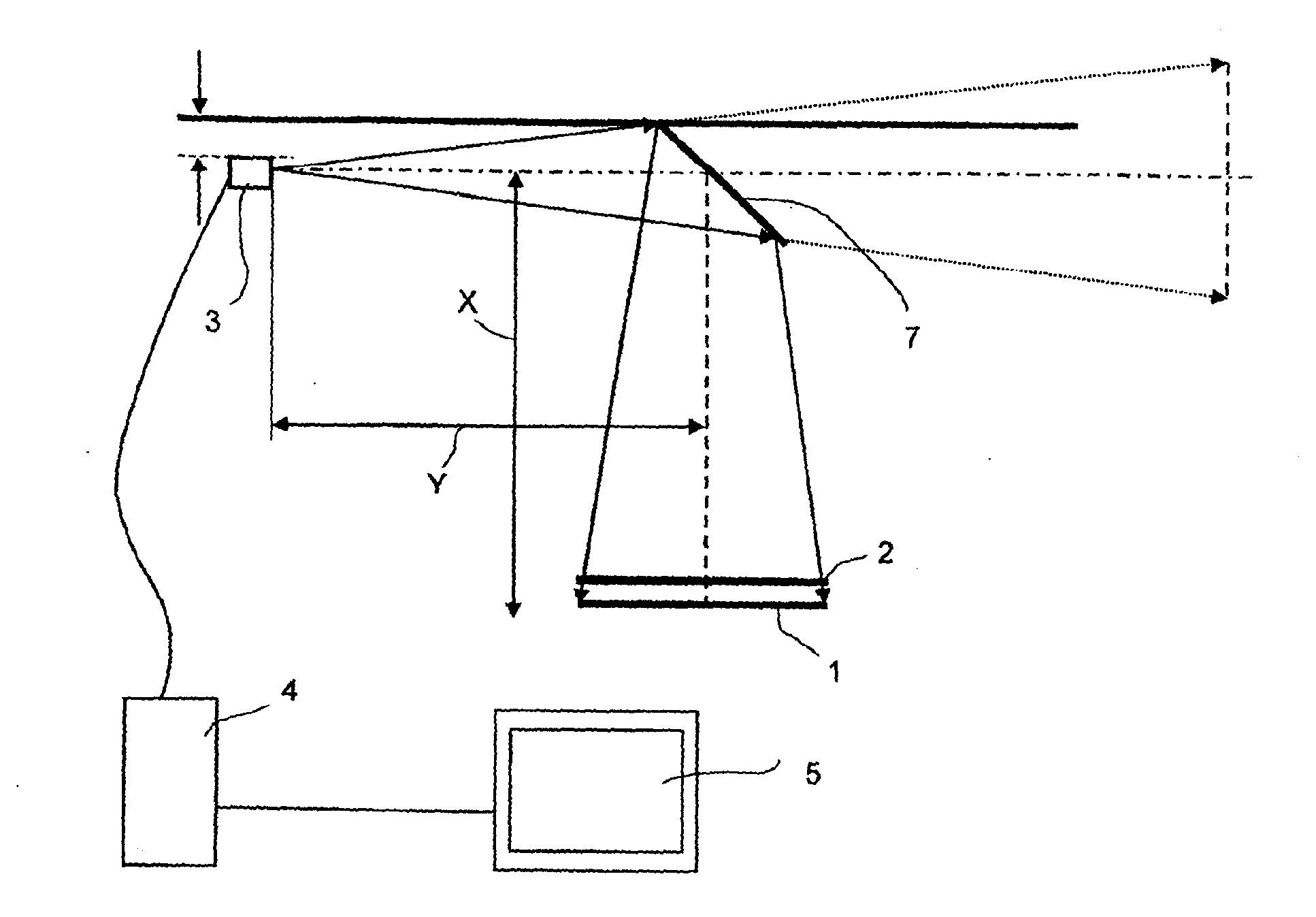
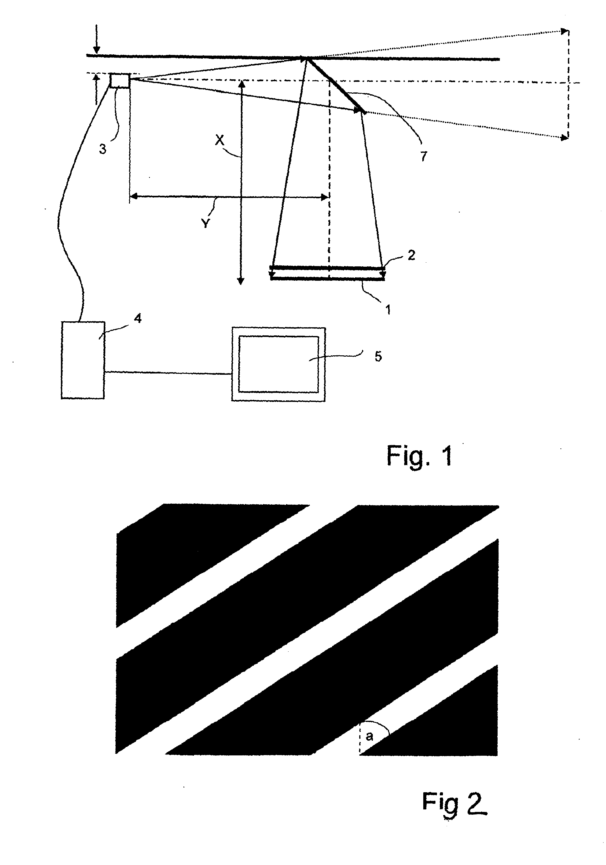
[0043]It is noted that the drawings are not to scale. This refers in particular also to the angular dimensions.

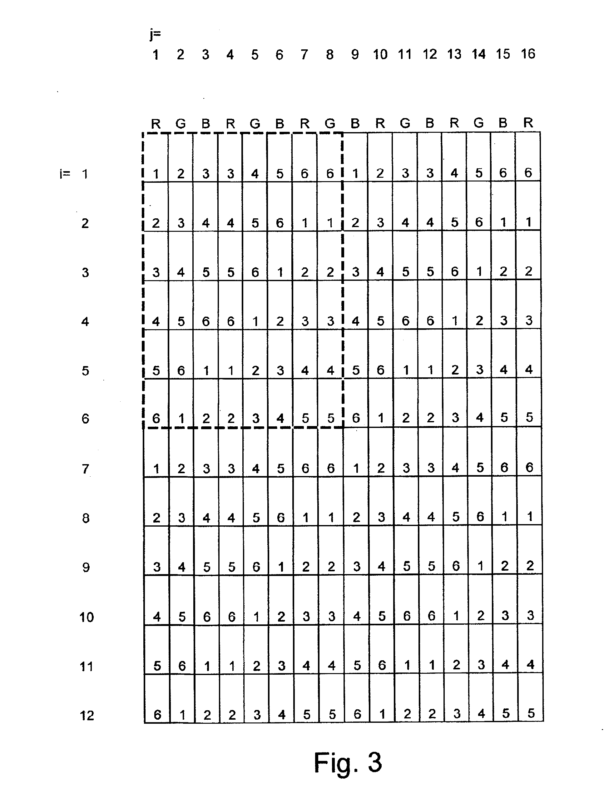
[0044]FIG. 1 shows the schematic structure for realizing the method of the invention. In this case, parallax barrier screen 2 is oriented at the distance s on a display screen 1 with pixels x(i,j) in a grid having rows i and columns j, as a result of which a display screen for three-dimensional representation arises. Furthermore, a camera 3 can be seen, which is suitable in general for taking two-dimensional pictures and whose output signal is supplied here, by way of example, by means of a frame grabber card to a computer 4. Computer 4 converts this signal accordingly and enables the display on a monitor 5.

[0045]The method of the invention is carried out in the following steps: First, a positioning marker 6a is applied temporarily approximately in the middle or the edges of the image area of display screen 1. Display screen 1 with positioning marker 6a is now recorded with...


PUM


Abstract

A method for orienting a parallax barrier screen on a display screen with picture elements x(i,j) in a grid comprising rows i and columns j for the purpose of producing a display screen for three-dimensional representation. This method includes the steps of: temporary application of a positioning marker, observation of the positioning marker by means of a camera, relative orientation of the display screen, removal of the positioning marker, positioning of the parallax barrier screen in front of the picture area of the display screen display of a test picture, which comprises various views, where k=1, . . . , n and n=6 or n=7, on the picture elements x(i,j) with rows i and columns j, observation of the displayed test picture through the parallax barrier screen by the camera, orientation of the parallax barrier screen in front of the display screen. The method according to the invention can be carried out quickly and is therefore suitable for industrial use for the manufacture of display screens for three-dimensional representation.

Description

[0001]This nonprovisional application is a continuation of International Application No. PCT / DE2007 / 002134, which was filed on Nov. 26, 2007, and which claims priority to German Patent Application No. 10 2007 047 470.0, which was filed in Germany on Sep. 28, 2007, and which are both herein incorporated by reference.BACKGROUND OF THE INVENTION[0002]1. Field of the Invention[0003]The invention relates to a method for orienting a parallax barrier screen on a display screen.[0004]2. Description of the Background Art[0005]Approaches to the field of parallax barriers have existed for some time. A pioneer in this field was Frederic Ives, who in the patent publication GB190418672 A proposed a system with a “line screen” for 3-D imaging. Further, fundamental findings on the use of barrier screens for 3-D imaging are described in the publication by Sam H. Kaplan “Theory of parallax barriers,” Journal of SMPTE, Vol. 59, No. 7, pp. 11-21, July 1952.[0006]A widespread dissemination of autostereo...

Claims


Application Information

Patent Timeline
IPC IPC(8): G01B11/27
CPCH04N13/0425H04N13/0409H04N13/31H04N13/327
Inventor SCHWARZ, JUERGENBERGMANN, LARSOTTE, STEPHANTORMA, FERENC
Owner WISE VISION HLDG
Why Eureka
Try Eureka