
LED testing apparatus and testing method thereof

a technology of testing apparatus and test method, which is applied in the direction of individual semiconductor device testing, image enhancement, instruments, etc., can solve the problems of reducing foreign substances may be infested, and the reliability of test results may be reduced

Active Publication Date: 2010-09-30
SAMSUNG ELECTRONICS CO LTD
View PDF2 Cites 24 Cited by
  • Summary
  • Abstract
  • Description
  • Claims
  • Application Information

AI Technical Summary

Benefits of technology

The present invention provides an LED testing apparatus and method that can automatically determine whether an LED is defective or not using visible rays or ultraviolet rays. The apparatus includes a first lighting unit, a second lighting unit, an image acquisition unit, and an LED state determination unit. The first lighting unit generates visible light to excite the LED, and the second lighting unit generates visible light to reflect off the LED. The image acquisition unit captures images of the LED, and the LED state determination unit analyzes the images to determine if the LED is defective or not. The apparatus can detect defects such as overflow, uncoating, foreign substances, and damage in the LED's encapsulant. The method involves performing image acquisition and LED state determination operations. The technical effects of the invention include improved reliability of LED testing and automation of the testing process.

Problems solved by technology

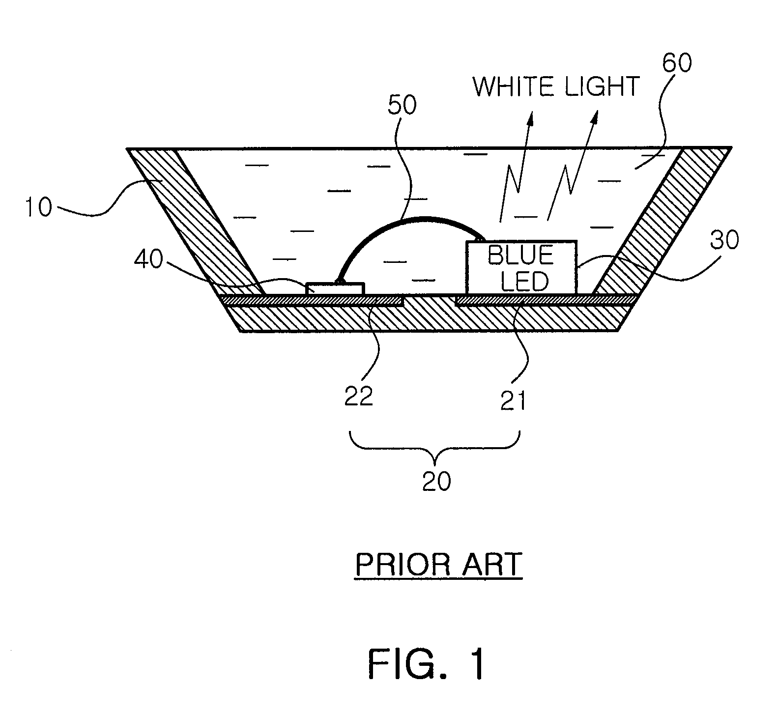
When the encapsulant is supplied, the bucket may not be coated with the encapsulant since the encapsulant is not properly supplied, or may overflow due to the excessive supply of the encapsulant.
The ingress of foreign substances or damage to the bucket may also occur in the process of supplying the encapsulant.
As for the test with the unaided eye, objective test criteria is ambiguous among inspectors, and the reliability of test results is reduced due to the difference in detection ability between skilled and unskilled inspectors.

Method used


Image

  • LED testing apparatus and testing method thereof
  • LED testing apparatus and testing method thereof
  • LED testing apparatus and testing method thereof

Examples


Embodiment Construction

[0039]Exemplary embodiments of the present invention will now be described in detail with reference to the accompanying drawings.

[0040]The invention may, however, be embodied in many different forms and should not be construed as limited to the embodiments set forth herein. Rather, these embodiments are provided so that this disclosure will be thorough and complete, and will fully convey the scope of the invention to those skilled in the art. In the drawings, the same reference numerals will be used throughout to designate the components having substantially the same configuration and function.

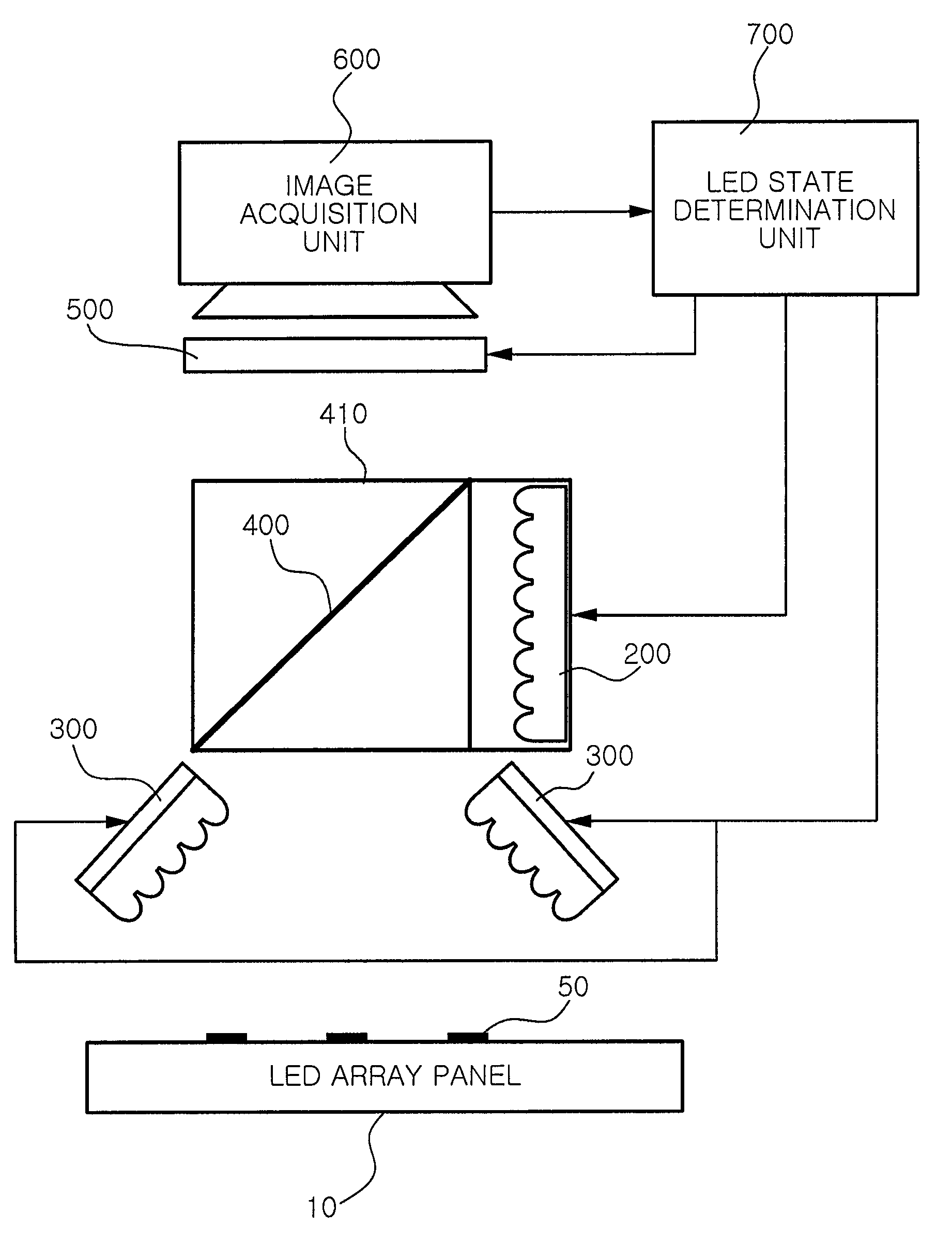
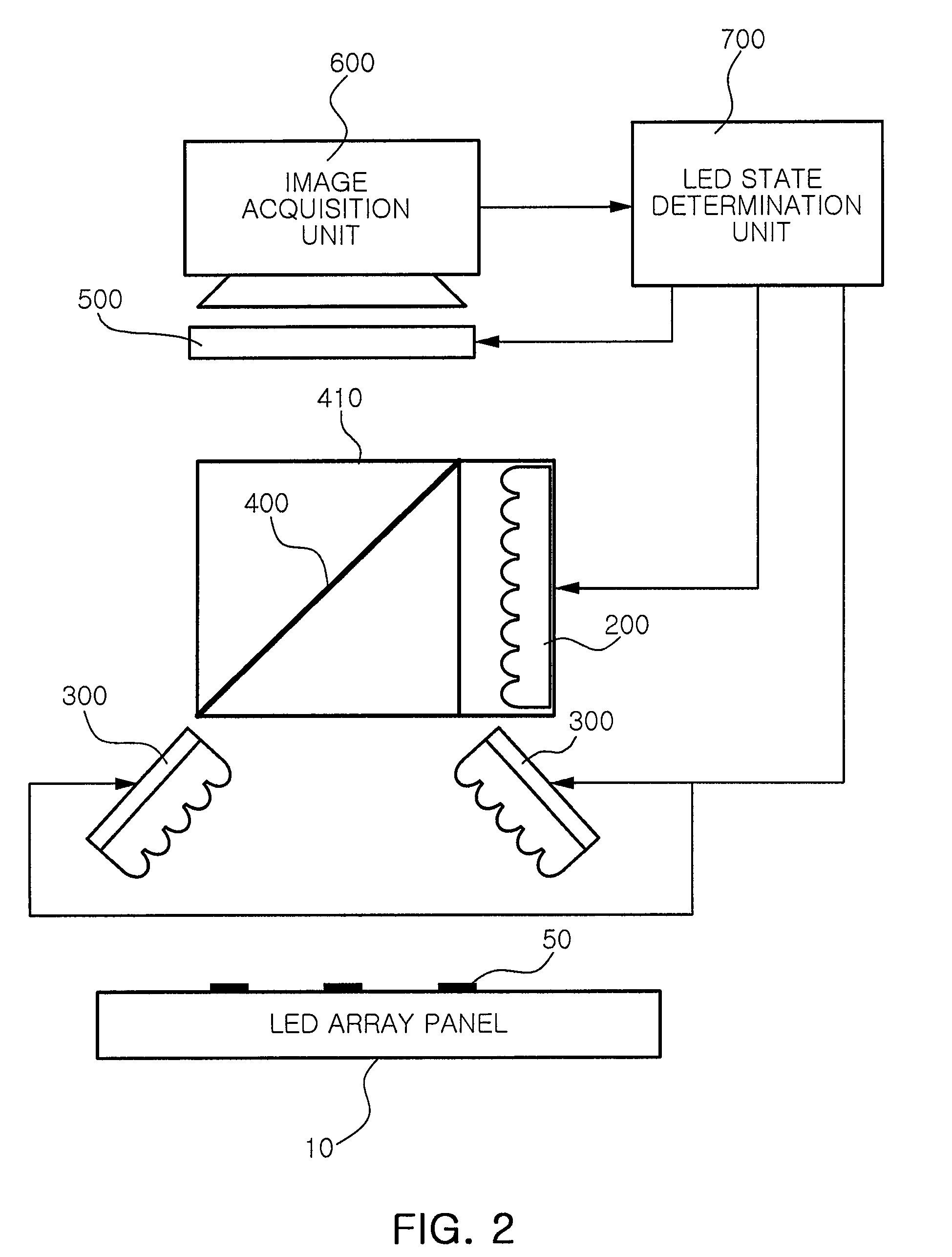
[0041]FIG. 2 is a block diagram illustrating the configuration of an LED testing apparatus according to an exemplary embodiment of the invention.

[0042]Referring to FIG. 2, an LED testing apparatus according to this embodiment has a first lighting unit 200, a second lighting unit 300, a color filter 500, an image acquisition unit 600, and an LED state determination unit 700. The first lighting ...


PUM


Abstract

There is provided an LED testing apparatus. An LED testing apparatus according to an aspect of the invention may include: a first lighting unit generating first light and irradiating the first light onto an LED having an encapsulant including a fluorescent material excited by the first light to emit light having a longer wavelength than the first light; a second lighting unit generating second light having a longer wavelength than the first light to irradiate the second light onto the LED; an image acquisition unit receiving the light emitted from the fluorescent material and the second light reflected off the LED to acquire images of the LED; and an LED state determination unit determining whether the LED is acceptable or defective using the images of the LED acquired by the image acquisition unit.There is further provided an LED testing method using the LED testing apparatus.

Description

BACKGROUND OF THE INVENTION[0001]1. Field of the Invention[0002]The present invention relates to an LED testing apparatus and a method thereof that can be applied to backlights or lighting devices, and more particularly, to an LED testing apparatus and a method thereof that can ensure the reliability of LED tests by automatically performing a test to determine whether an LED is acceptable or defective, using visible rays or ultraviolet rays.[0003]2. Description of the Related Art[0004]In general, light emitting diodes (LEDs) refer to semiconductor devices that emit light of various colors by configuring light sources by altering the compound semiconductor material, such as GaAs, AlGaAs, GaN or InGaInP.[0005]High-brightness, high-quality LED products rather than general-purpose, low-brightness LED products can be manufactured in line with the rapid progress in semiconductor technology. Furthermore, thanks to the realization of blue and white LEDs having excellent properties, the appl...

Claims


Application Information

Patent Timeline
Patent Type & Authority Applications(United States)
IPC IPC(8): G06K9/00G06V10/143
CPCG01R31/2635G01R31/2656G06T2207/30148G06T7/0004G06K9/2018G06V10/143
Inventor JI, WON SOOLEE, WOOK HEESONGCHO, CHONG WOOKKIM, SUNG JAEYUN, YOUNG SUKIM, HONG MIN
Owner SAMSUNG ELECTRONICS CO LTD
Learn More