
Bearing Apparatus Featuring Electrorheological Fluid Lubrication

a technology of electrorheological fluid and bearing, which is applied in the direction of bearings, mechanical apparatus, crankshafts, etc., can solve the problems of reducing the ability of the film to function as a lubricant release agent, affecting the performance of the bearing, so as to reduce facilitate the removal and replacement and control the viscosity of the electrorheological fluid

Inactive Publication Date: 2010-09-30
THE UNITED STATES OF AMERICA AS REPRESENTED BY THE SECRETARY OF THE NAVY
View PDF11 Cites 5 Cited by
  • Summary
  • Abstract
  • Description
  • Claims
  • Application Information

AI Technical Summary

Benefits of technology

[0014]Depending on the inventive embodiment, other inventive features include: reducing the viscosity of the electrorheological fluid (as by ceasing electrification thereof) to facilitate removal and replacement of the electrorheological fluid; controllably changing the magnitude of electrification of the electrorheological fluid (e.g., in terms of voltage or current) so as to controllably change the viscosity of the electrorheological fluid; controllably changing the magnitude of electrification of the electrorheological fluid (e.g., in terms of voltage or current) in one or more selected regions of the bearing so as to controllably vary the viscosity of the electrorheological fluid from region to region. The present invention affords easy lubricant replacement in bearing applications requiring high viscosity lubricant during operation. The present invention maintains higher viscosity of the ERF lubrication during operation by energizing the ERF lubricant, and reduces the viscosity of the ERF lubrication (thereby facilitating drainage / emptying of the ERF lubricant) by refraining from energizing the ERF lubricant. The viscosity of the ERF lubricant can be controllably altered during operation in order to promote better performance. The viscosity of one or more specific regions of the ERF lubricant can be controllably varied while the viscosity of the ERF lubricant in one or more other regions is held constant; in this manner, the present invention succeeds in controlling the pressure distribution over various arc-lengths of a circular bearing such as a rolling element bearing or journal bearing.
[0015]According to frequent inventive practice, the ERF lubricant is energized during operation so that a high viscosity is maintained. When the electrorheological fluid lubricant needs to be replaced (e.g., is excessively old or used), a portal in the bearing housing is opened after the electric field is shut off. Turning off the electric field enables the old / used lubricant to freely flow out of the portal and also enables new, fresh electrorheological fluid lubricant to be introduced into the bearing housing. The “de-energizing” of the electrorheological fluid lubricant reduces the viscosity, thereby enabling free flow of the old / used lubricant out of the bearing through the portal. The new, fresh electrorheological fluid lubricant is non-electrified and therefore flows easily into the bearing. Moreover, in accordance with the present invention, the viscosity of the ERF lubricant can be controllably changed in response to changes in temperature of the bearing. During operation of the inventive bearing apparatus, the speed of rotation may vary; hence, the temperature due to frictional heating may vary. Generally, with regard to inventive adjustment of the ERF lubricant, a consideration shared by the various modes of inventive practice is that the viscosity of the ERF lubricant should be sufficiently high that ERF lubricant remains in the desired location or locations, but should not be excessively high whereby ERF lubricant hinders the relative rotational motion of the relatively rotating components (e.g., the outer race and the inner race in first-mode, second-mode, and third-mode inventive practice; or, the journal bearing member and the shaft in fourth-mode inventive practice).

Problems solved by technology

Bearings are frequently the first component of equipment to fail.
Failure of rolling element bearings (e.g., ball bearings or roller bearings), for instance, is commonly associated with tribological effects (e.g., “wear and tear”) when insufficient lubrication is applied to the surfaces of the rolling elements (e.g., balls or rollers).
A disadvantage of this methodology is that, over time, the film releases all of its lubricant; the film itself becomes “lubricant starved.” Another disadvantage is that the properties of the film degrade over time due to polymer aging effects.
The compression of the rolling element accelerates the aging effects, which consequently degrade the capabilities of the film to function as a lubricant-releasing agent.
A disadvantage of this methodology is that, once the mist has been deposited onto the race, it is then free to flow from and / or drip off the race; that is, the lubricant is not “secured” to the surface of the race, but can leave the race due to the action of gravity.
A disadvantage is that the solid lubricant of Ryan et al. functions as a result of wearing away; that is, small particles of solid lubricant are shaved off of the coating by the rolling element as the rolling element moves along race surface.
The coating is eventually worn away because the number of particles shaved off increases over time.
's coating is worn away, the increasing clearance between the rolling elements and the races leads to problems relating to vibration.
The bearing lubrication approaches of Takasaki et al. and Hashimoto are disadvantageous similarly as is that of Brackett.
A disadvantage of Stephens' microstructures is that, since the surfaces they form are uneven (unsmooth), the distribution of compression forces acting on a bearing element, and hence the wear of the bearing element, is uneven.
The surface areas formed by the “peaks” (highest elevations) of the microstructures are subjected to higher compression forces, and hence are prone to greater wear, than are the less elevated surface areas.

Method used


Image

  • Bearing Apparatus Featuring Electrorheological Fluid Lubrication
  • Bearing Apparatus Featuring Electrorheological Fluid Lubrication
  • Bearing Apparatus Featuring Electrorheological Fluid Lubrication

Examples


example 1

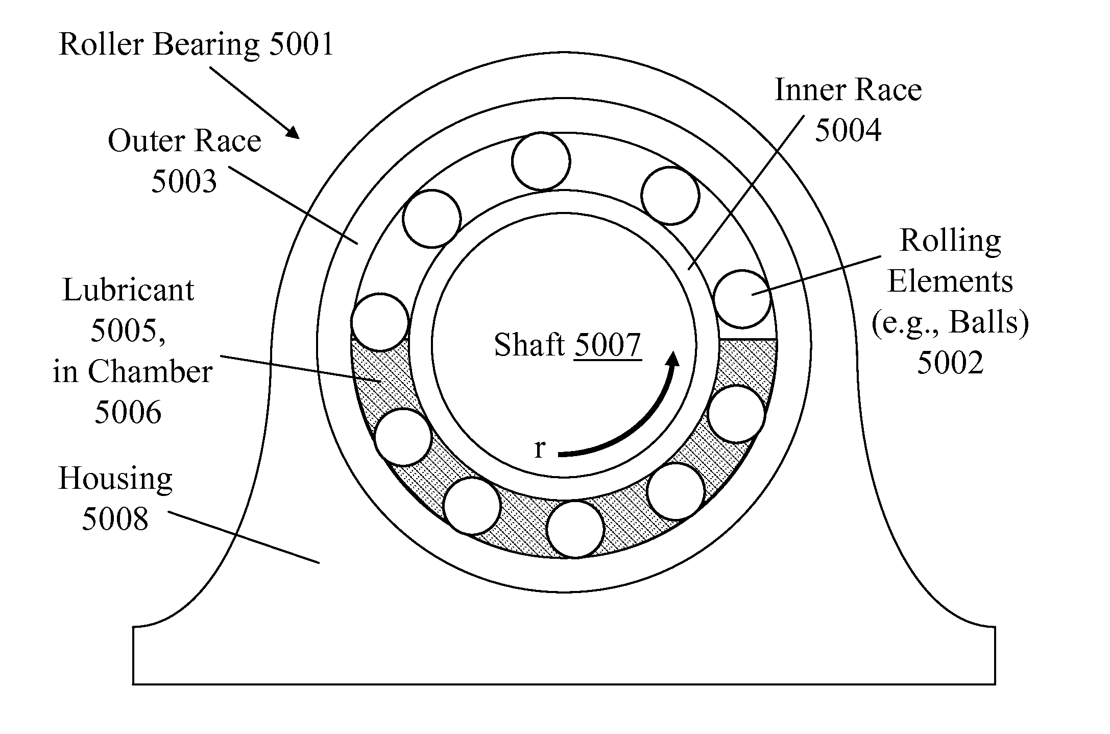
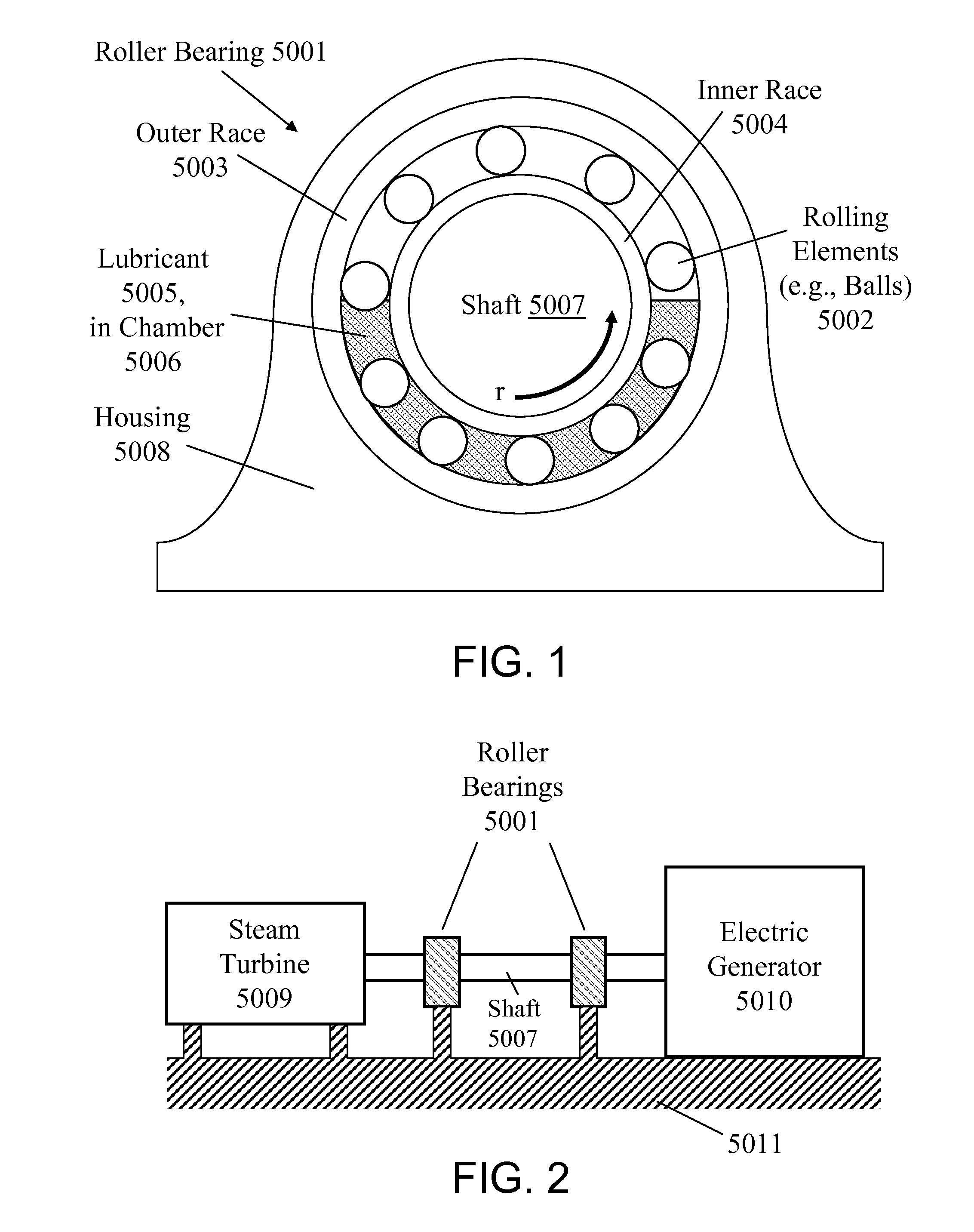
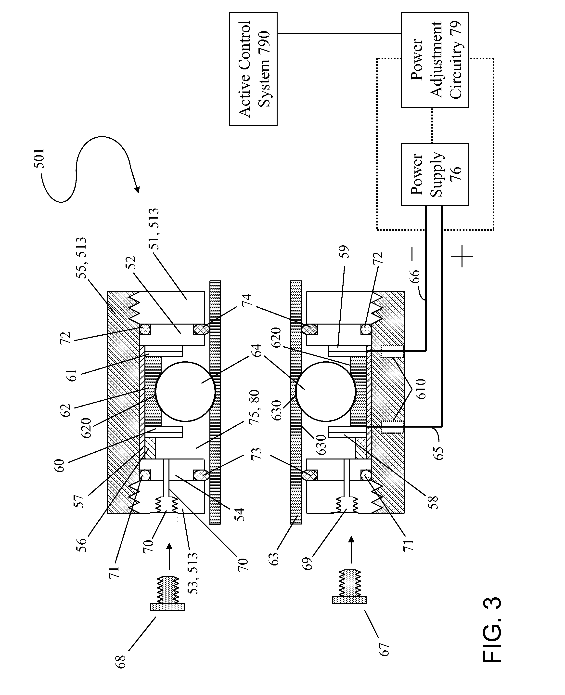
[0043]A first mode of the present invention is typically practiced so as to describe a kind of ball bearing pillow block arrangement similar to that shown in FIG. 1. According to the first inventive mode, the ERF lubricant is held in position, by means of an electric field, onto either or both of the inner and outer races. The inventive rolling element bearing apparatus is configured with two electrodes suitable for electrically holding the ER fluid in position on a raceway surface. As a rolling element moves over the raceway surface, it pushes most of the ERF lubricant out of its path, except for a thin lubricant layer that remains between the rolling element and the raceway surface. The inventive rolling element bearing is lubricated primarily by virtue of the lubricant layer coating the raceway surface.

[0044]The inventive embodiment described herein with reference to FIG. 3 and FIG. 4 involves a horizontal rotating shaft, a circular bearing element path defining a vertical geomet...

example 2

[0055]Referring now to FIG. 5 and FIG. 6, inventive ball bearing apparatus 502 includes electrically conductive outer race 62, electrically conductive inner race 63, electrically nonconductive balls 64, electrorheological fluid lubricant 80, electrically conductive retainer (spacer) 90, electrical power supply 76, electrode wires 65 and 66, and electrical connector 69. Balls 64 are spaced apart from each other by retainer 90. Balls 64 are electrically nonconductive (e.g., made of ceramic). Electrical wire 65 and electrical wire 66 (via electrical connector 69) connect power supply 76 to outer race 62 and inner race 63, respectively. As shown in FIG. 5, electrical connector 69 (e.g., a leaf spring or brush) is attached at the end of electrical wire 66 and makes electrical contact with the rotating inner race 63. Inventive ball bearing apparatus 502 also includes a fluid-tight housing, such as housing 513 shown in FIG. 3 and FIG. 4, which defines a fluid-tight chamber 75, which enclos...

example 3

[0060]First-mode inventive practice (such as exemplified by Example 1) and second-mode inventive practice (such as exemplified by Example 2) involve the so-called “Winslow effect.” According to inventive practice in which the “Winslow” effect is manifest, an electric field that is generated between two electrodes upon the electrification thereof results in the holding therebetween (i.e., between the respective electrode surfaces facing each other) of ERF fluid 80. As distinguished from Examples 1 and 2, the so-called “edge effects” are exhibited in Example 3 (which exemplifies third-mode inventive practice) and Example 4 (which exemplifies fourth-mode inventive practice).

[0061]Reference is now made to FIG. 7, FIG. 8, FIG. 9 and FIG. 10, which are illustrative of third-mode inventive practice. As shown in FIG. 7, each embedded electrode 200 is embedded in outer race 62 and has an electrode tip (longitudinally extreme edge) 201 that is even (flush) with the inward facing raceway surfa...


PUM


Abstract

The present invention, as variously practiced, implements electrorheological fluid (ERF) as a bearing lubricant. Various modes of an inventive rolling element bearing apparatus provide for electrification of inventive electrode components, viz: (first mode) two annular disk electrodes, opposite each other and perpendicular to the two raceway surfaces; or, (second mode) electrically conductive inner and outer races, having an electrically conductive spacer therebetween; or, (third mode) plural electrodes, radially embedded in a race. An ERF lubricative coating remains on one or both raceway surfaces in accordance with Winslow effect principle (first and second modes) or edge effect principle (third mode). An inventive journal bearing apparatus provides for electrification of electrodes that are axially-longitudinally embedded in a journal bearing member, resulting in establishment of edge effect electric flux lines between adjacent electrode pairs, an ERF lubricative coating thereby remaining on the journal bearing member's inward facing surface, contiguous to the shaft.

Description

CROSS-REFERENCE TO RELATED APPLICATIONS[0001]This application is a continuation of U.S. nonprovisional patent application Ser. No. 11 / 890,105, filing date 24 Jul. 2007, now U.S. Pat. No. 7,736,063, issue date 15 Jun. 2010, hereby incorporated herein by reference, entitled “Bearing Apparatus Having Electrorheological Fluid Lubricant,” joint inventors Ronald P. Reitz and Gus F. Plangetis.STATEMENT OF GOVERNMENT INTEREST[0002]The invention described herein may be manufactured and used by or for the Government of the United States of America for governmental purposes without payment of any royalties thereon or therefor.BACKGROUND OF THE INVENTION[0003]The present invention relates to bearings, more particularly to methodologies (such as involving lubrication) for reducing adverse effects (such as wear) associated with frictional contact characterizing bearing operation.[0004]Bearings are used in a wide variety of machinery, including motors and other rotating machines. Bearings are freq...

Claims


Application Information

Patent Timeline
Patent Type & Authority Applications(United States)
IPC IPC(8): F16C33/10
CPCF16C41/002F16C33/6688F16C33/109
Inventor REITZ, RONALD P.PLANGETIS, GUS F.
Owner THE UNITED STATES OF AMERICA AS REPRESENTED BY THE SECRETARY OF THE NAVY
Learn More