Non-linearity compensation in an optical transmission

a technology of optical transmission and non-linearity compensation, applied in the field of optical communication, can solve the problems of limiting the distance over which data may be transmitted in single-mode optical fibres before some form of regeneration is required, affecting the overall non-linear compensation of optical channels, and affecting the quality of received signals, so as to improve the overall non-linear compensation, and reduce the effect of optical channel non-linearity

Active Publication Date: 2010-09-30
MONASH UNIV
View PDF16 Cites 74 Cited by
  • Summary
  • Abstract
  • Description
  • Claims
  • Application Information

AI Technical Summary

Benefits of technology

[0013]applying the information-bearing signal and the time-varying phase modulation to an optical source to generate a corresponding transmitted optical signal having substantially said transmitted optical power characteristic, wherein said first function of transmitted optical power is selected so as to mitigate the effect of the non-linearity of the optical channel upon the transmitted optical signal.
[0066]However, it will be appreciated that improvements in received signal quality may be achieved using only pre-compensation or only post-compensation, and that such arrangements are also within the scope of the present invention. In particular, the relative benefits of pre- and post-compensation have been found to depend upon the particular optical modulation format applied to the transmitted optical signal, and it is an advantageous feature of the present invention that, in various embodiments thereof, improvements in the quality of signals received over non-linear optical channels may be achieved using a variety of arrangements, enabling various technical factors and cost considerations to be traded off against overall improvements in signal quality.

Problems solved by technology

The distance over which data may be transmitted in single-mode optical fibres before some form of regeneration is required may be limited by optical attenuation and / or various dispersion mechanisms.
This is particularly true in long-haul optical transmission systems, where there is an inherent trade-off between the peak optical power (ie intensity within the single-mode fibre core) and the overall system cost.
However, the use of high launch powers increases the effect of optical non-linearities, resulting in higher optical signal distortion, which ultimately limits the received signal quality, and thus the maximum transmission distance achievable before the signal must be detected, recovered and regenerated.
Compensating for non-linear transmission impairment is generally more difficult than compensating for linear processes such as chromatic dispersion.
However, past attempts to apply this idea have proven to be impractical, computationally difficult, and / or have provided only relatively small improvements in received signal quality.
Unfortunately, it has thus far proven impractical to manufacture and deploy components utilising materials with the required non-linear properties.
The difficulty with this approach is that it is initially necessary to determine the required characteristics of the effective negative non-linearity.
This approach is limited by the difficulties inherent in obtaining sufficiently accurate information regarding the actual transmission system, and also by the high computational complexity of modelling the inverse system.
These are generally relatively complex approaches utilising non-linear feedback systems, or the use of optical modulators operated in response to the received optical power in order to simulate a negative non-linear coefficient.

Method used


Image

  • Non-linearity compensation in an optical transmission
  • Non-linearity compensation in an optical transmission
  • Non-linearity compensation in an optical transmission

Examples


Embodiment Construction

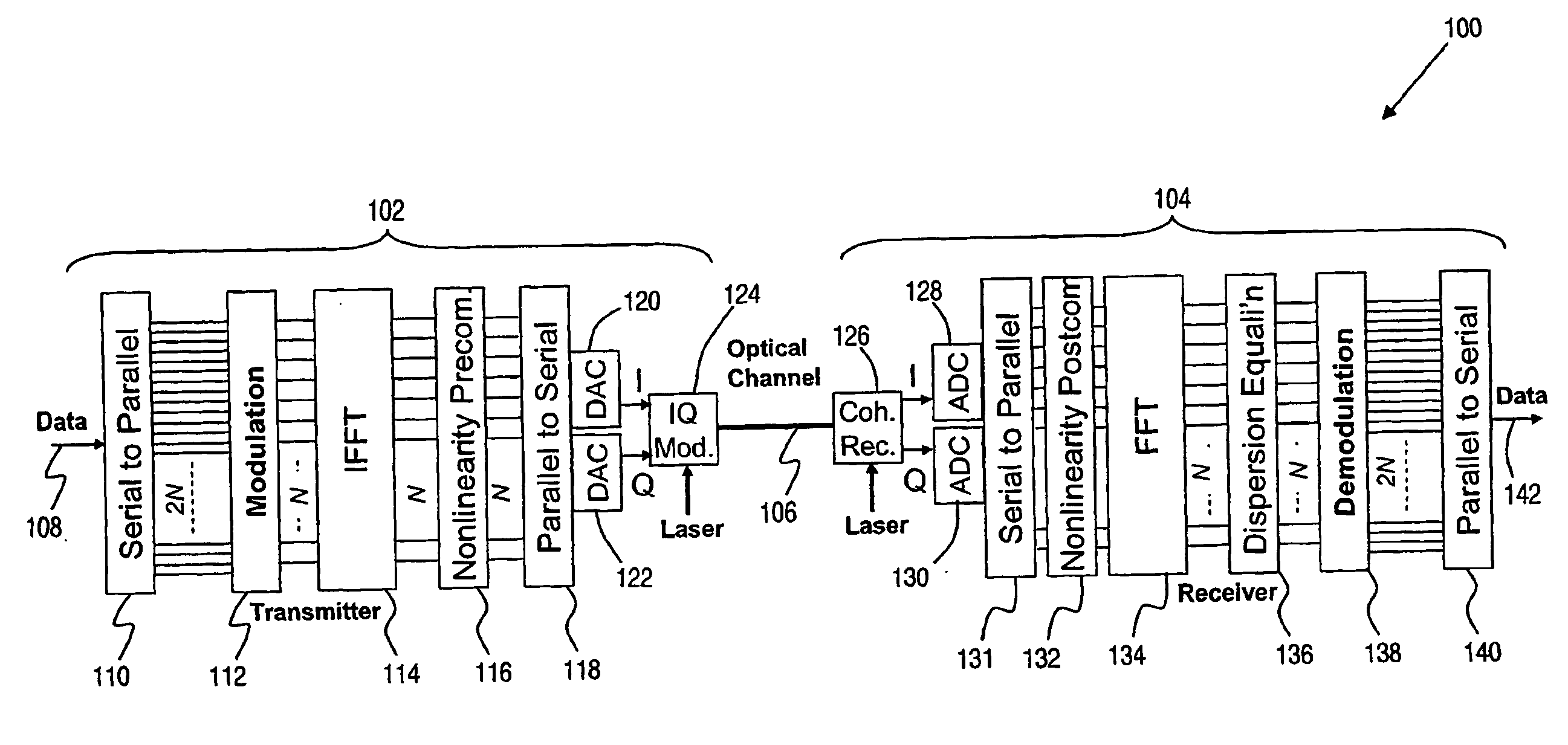
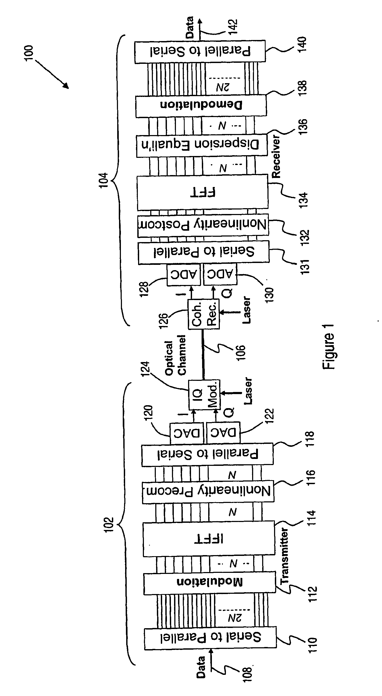
[0078]Turning first to FIG. 1, there is shown schematically a system 100 for communicating digital information over a non-linear optical channel according to a preferred embodiment of the present invention. While the invention is exemplified herein by the system 100, which employs orthogonal frequency division multiplexing (OFDM) in encoding and modulating digital signals for transmission over the optical channel, it is to be understood that the invention is not limited to this particular embodiment. Rather, embodiments of the invention are characterised generally by the generation of an information-bearing signal which includes a plurality of closely-spaced sub-carriers when represented in the frequency domain, the application of a time-varying phase modulation which is a function of a transmitted optical power characteristic corresponding with the information-bearing signal, and the application of the information-bearing signal and the time-varying phase modulation to an optical s...


PUM


Abstract

A method of transmitting information over a non-linear optical channel includes the step (152) of generating an information-bearing signal, preferably an OFDM signal, which includes a plurality of closely-spaced sub-carriers in the frequency domain. A time-varying phase modulation is determined (154), which is a first function, and preferably a linear function, of the transmitted optical power corresponding with the information-bearing signal. The information-bearing signal and the time-varying phase modulation are applied (156) to an optical source in order to generate a corresponding transmitted optical signal having substantially the stated transmitted optical power characteristic. The first function of transmitted optical power is selected so as to mitigate the effect of the non-linearity of the optical channel upon the transmitted optical signal. In alternative arrangements, a time-varying phase modulation, being a second function of optical power, is computed (162) and applied (164) to a signal received following transmission through a non-linear optical channel. The two alternative arrangements provide, respectively, for pre-compensation and post-compensation of non-linear propagation effects that may be carried out entirely within the electrical domain, for example using digital signal processing techniques.

Description

FIELD OF THE INVENTION[0001]The present invention relates generally to optical communications, and more particularly to methods and apparatus for the generation, transmission, detection and decoding of optical signals in order to compensate for the effects of optical non-linearities existing in optical channels, and particularly optical fibres, which affect the quality of signals transmitted at high power levels and / or over long distances.BACKGROUND OF THE INVENTION[0002]Optical transmission, in which an information signal is modulated onto an optical carrier, is widely employed in modern communication systems. In particular, wide-area communications networks employ long-haul transmission links using single-mode optical fibres for the transmission of digital information at very high bit rates, using one or more optical carriers, or wavelengths, over each fibre. The distance over which data may be transmitted in single-mode optical fibres before some form of regeneration is required ...

Claims


Application Information

Patent Timeline
Patent Type & Authority Applications(United States)
IPC IPC(8): H04J14/02H04B10/04
CPCH04B10/2543H04B2210/254H04L25/03343H04L27/2096H04B10/6163H04L27/367H04L2025/03414H04L27/2697H04L27/2627H04B10/25H04B10/50H04B10/58
Inventor LOWERY, ARTHURDU, LIANG BANGYUAN
Owner MONASH UNIV
Why Eureka
Try Eureka