

Ink feeder for felt-tip ink pen
a felttip ink pen and feeder technology, which is applied in the direction of ink reservoir pens, coatings, printing, etc., can solve the problems of not being able to handle along with other components using a machine, troublesome and time-consuming, and not being able to keep the ring-shaped sponge non-deformed, etc., and achieves the effect of easy introduction
- Summary
- Abstract
- Description
- Claims
- Application Information
AI Technical Summary
Benefits of technology
Problems solved by technology
Method used
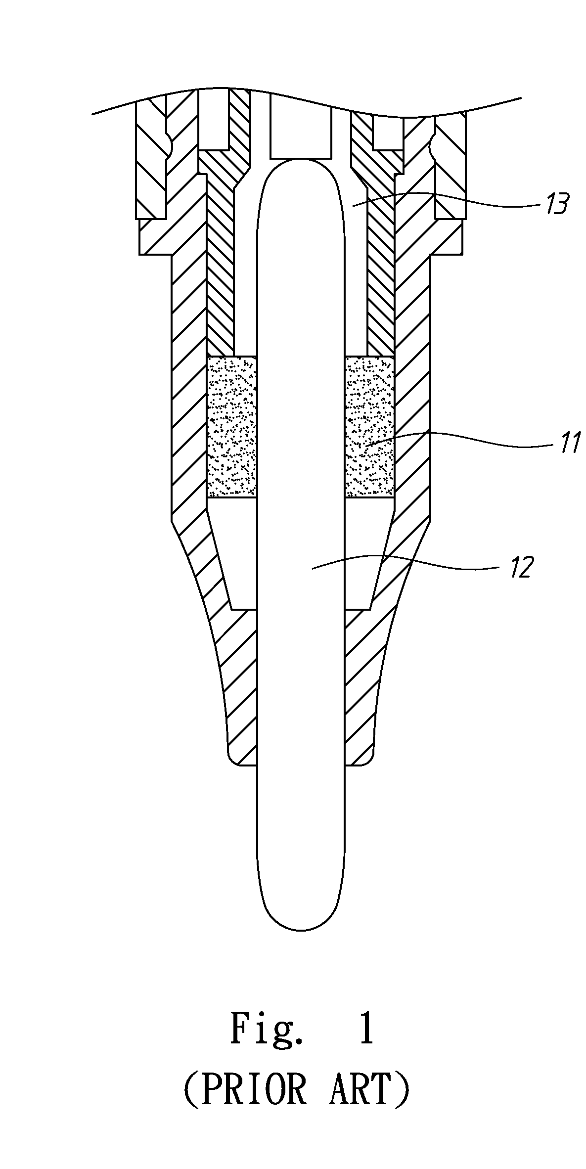
Image

Examples
Embodiment Construction
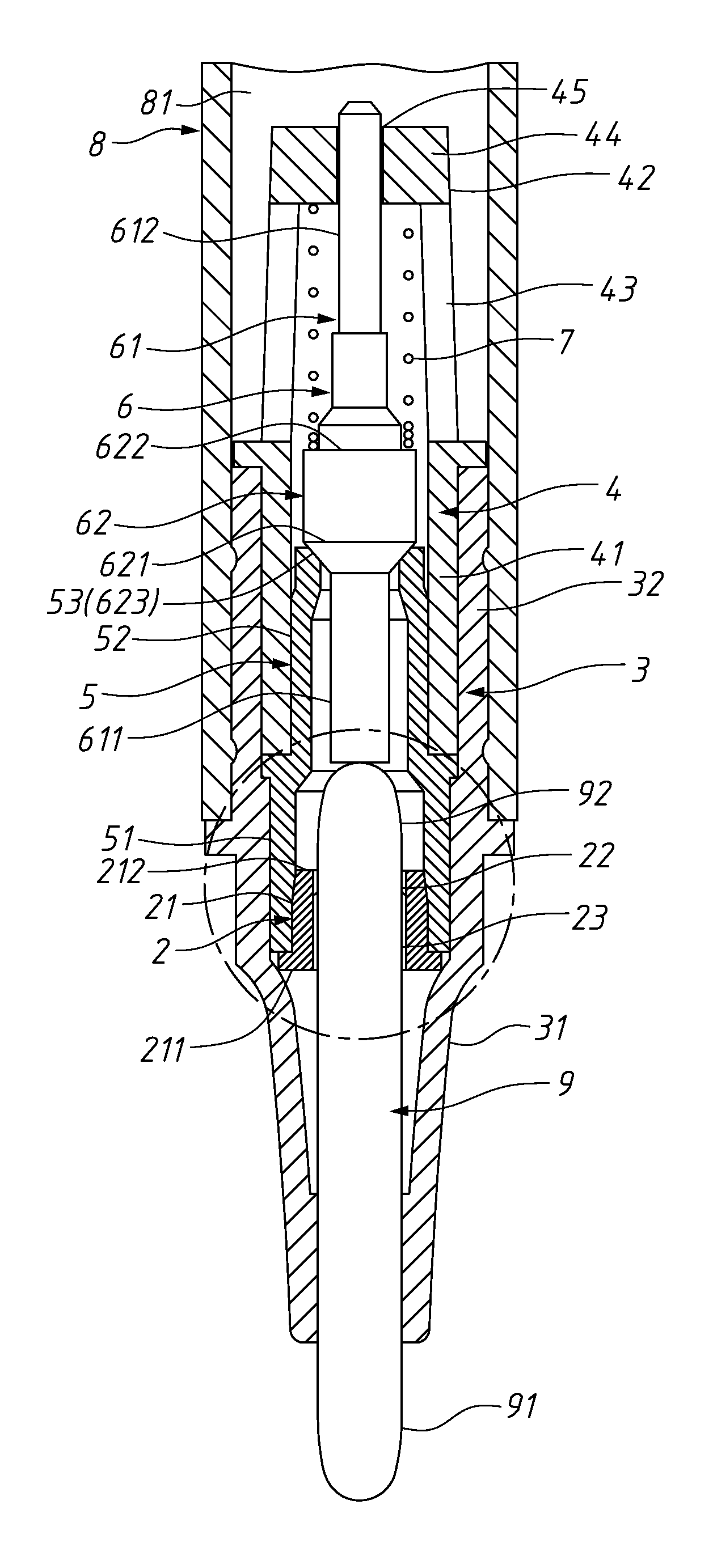
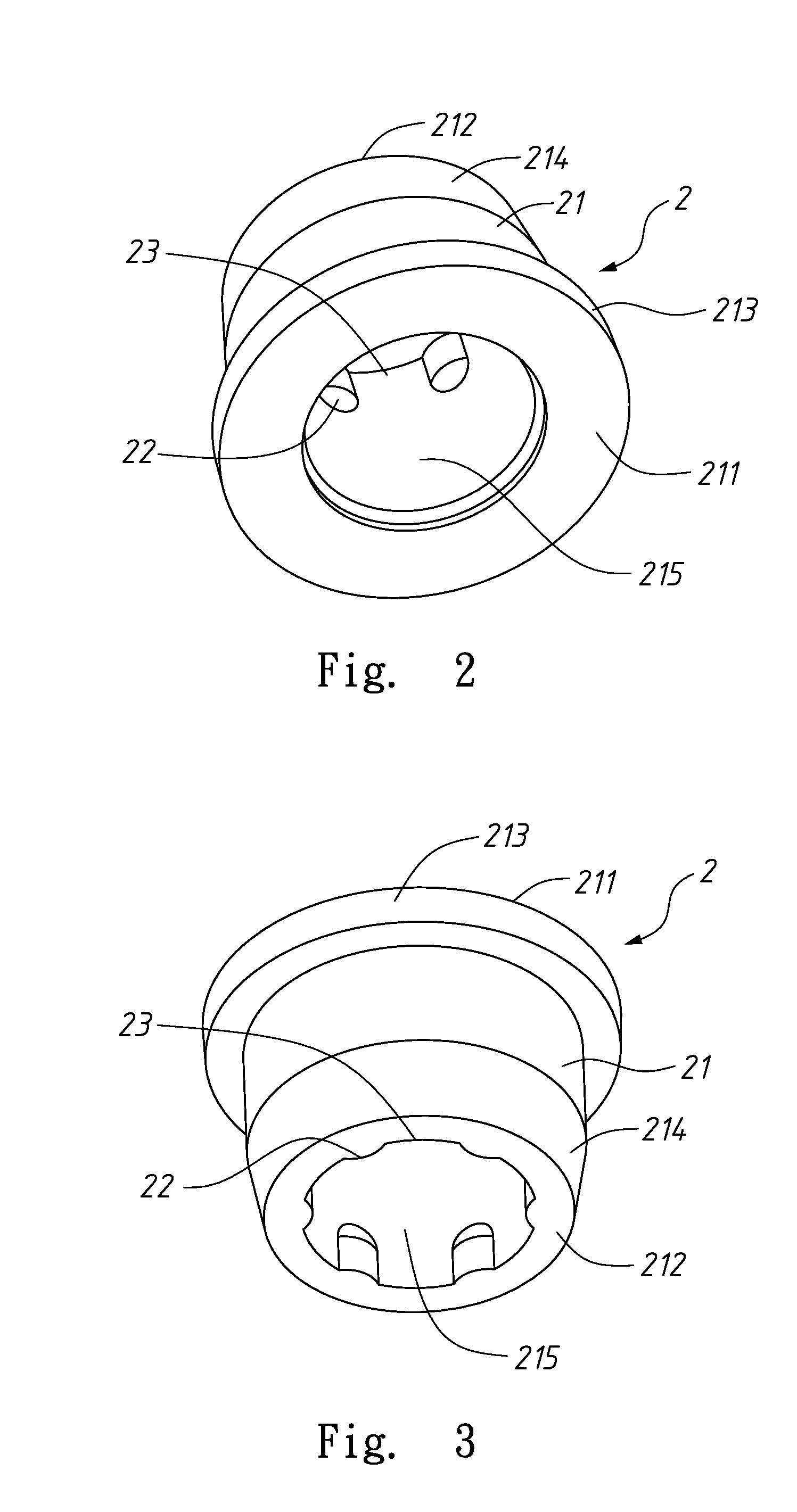
[0029]Please refer to FIGS. 2 and 3 that are two perspective views of an ink feeder 2 for felt-tip ink pen according to a preferred embodiment of the present invention, being viewed from two different view angles.
[0030]As can be seen from FIGS. 2 and 3, the ink feeder 2 includes a main body 21, a plurality of micro raised portions 22, and a plurality of ink feeding clearances 23.
[0031]The main body 21 is made of a rigid material, such as a plastic material, and has a first end portion 211 and a second end portion 212 opposite to each other. The first end portion 211 is formed at a lower end into a radially outward extended flange 213. An outer peripheral wall surface of the second end portion 212 is upward tapered to form a conical surface 214. The main body 21 internally defines a feeding bore 215.
[0032]A plurality of micro raised portions 22 is radially inward protruded from and circumferentially spaced along an inner wall surface of the main body 21. The micro raised portions 22 ...
PUM
 Abstract
Description
Claims
Application Information