Exchangeable cutting head and cutting tool having the same

Active Publication Date: 2010-09-30
MITSUBISHI MATERIALS CORP
View PDF5 Cites 20 Cited by
  • Summary
  • Abstract
  • Description
  • Claims
  • Application Information

AI Technical Summary

Benefits of technology

[0072]Consequently, it is possible to easily connect the cutting head body with the connection member.
[0073]In addition, since the connection structure constitute

Problems solved by technology

In addition, it is possible to solve a problem in tha

Method used


Image

  • Exchangeable cutting head and cutting tool having the same
  • Exchangeable cutting head and cutting tool having the same
  • Exchangeable cutting head and cutting tool having the same

Examples


first embodiment

[0088]Hereinafter, a first embodiment of the present invention will be described with reference to drawings.

[0089]In the explanation below, a position which is close to the front-end position is referred to as “a front-end side (front-end section)” in a direction from a rear-end position to toward a front-end position. In this case, a rear-end face 15 (described below) of a tool body 10 is formed at the rear-end position, and a cutting edge 23B (described below) is formed at the front-end position.

[0090]In addition, a position which is close to the rear-end position is referred to as “rear-end side (rear-end, rear-end section)” in a direction from the front-end position toward the rear-end position.

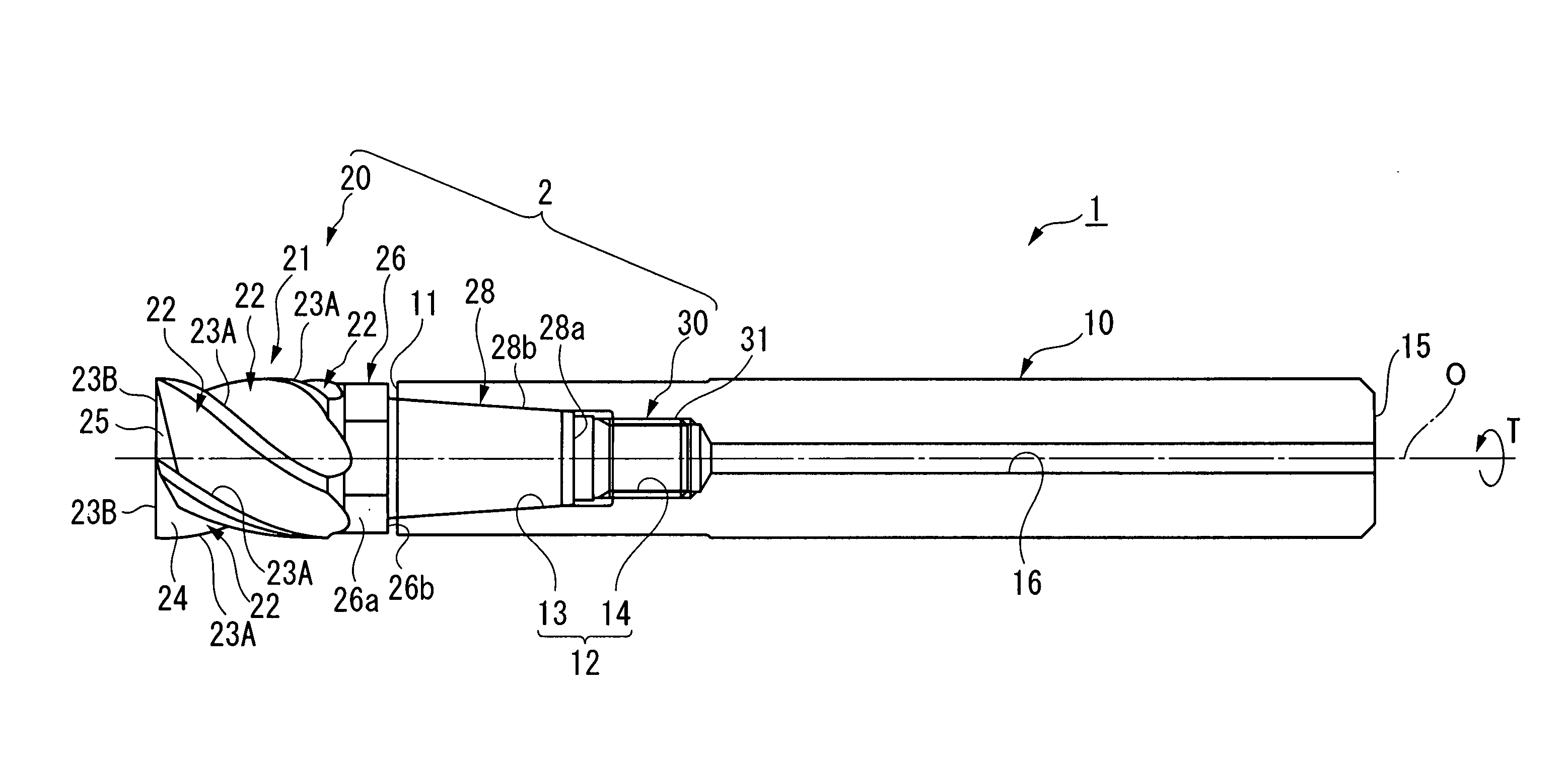
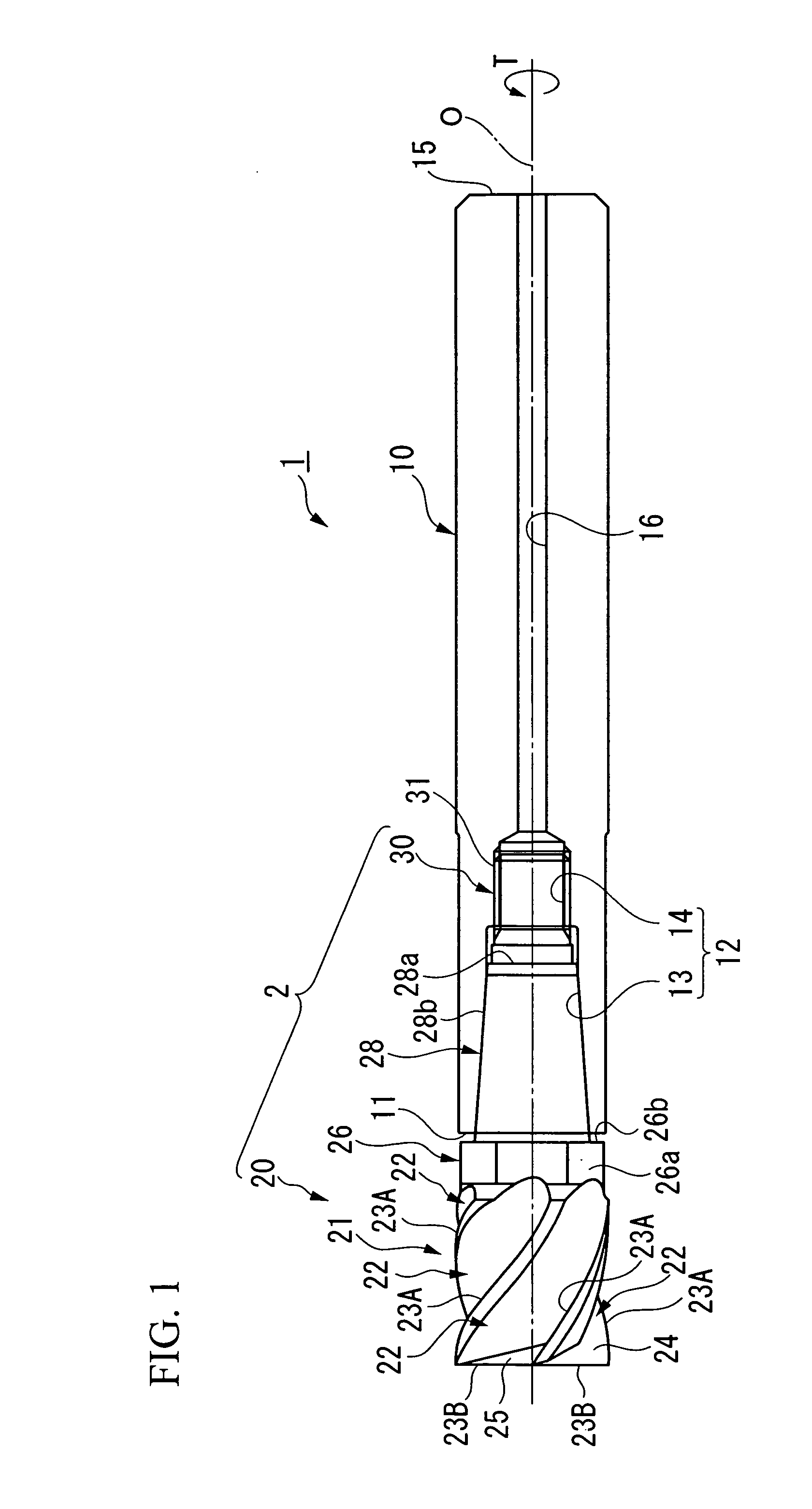
[0091]As shown in FIG. 1, a cutting tool 1 having an exchangeable cutting head of a first embodiment is constituted of a tool body 10 and an exchangeable cutting head 2.

[0092]The tool body 10 rotates around a center line O.

[0093]The exchangeable cutting head 2 is constituted of a cutting ...

second embodiment

[0265]Next, a cutting tool 80 having an exchangeable cutting head of a second embodiment of the present invention will be described with reference to FIGS. 7 and 8.

[0266]In FIGS. 7 and 8, identical symbols are used for the elements which are identical to those of the cutting tool 1 of the first embodiment, and the explanations thereof are omitted or simplified.

[0267]In the cutting tool 80 of the second embodiment, a cutting head body 81 has a wrench engagement section 86 (rotation section).

[0268]A wrench engagement section 86 has an outer-peripheral face formed as a center circular cylinder around the center line O.

[0269]A portion of the outer-peripheral face is machined in a direction parallel to the center line O and in a direction from the outer-peripheral face to the center line O by a predetermined depth.

[0270]Consequently, the outer-peripheral face of the wrench engagement section 86 has two pairs of parallel faces 86a (notched face).

[0271]In the circumferential direction, a c...

third embodiment

[0321]Next, a cutting tool 100 having an exchangeable cutting head of a third embodiment of the present invention will be described with reference to FIGS. 12 and 13.

[0322]In FIGS. 12 and 13, identical symbols are used for the elements which are identical to those of the cutting tool 1 of the first embodiment, and the explanations thereof are omitted or simplified.

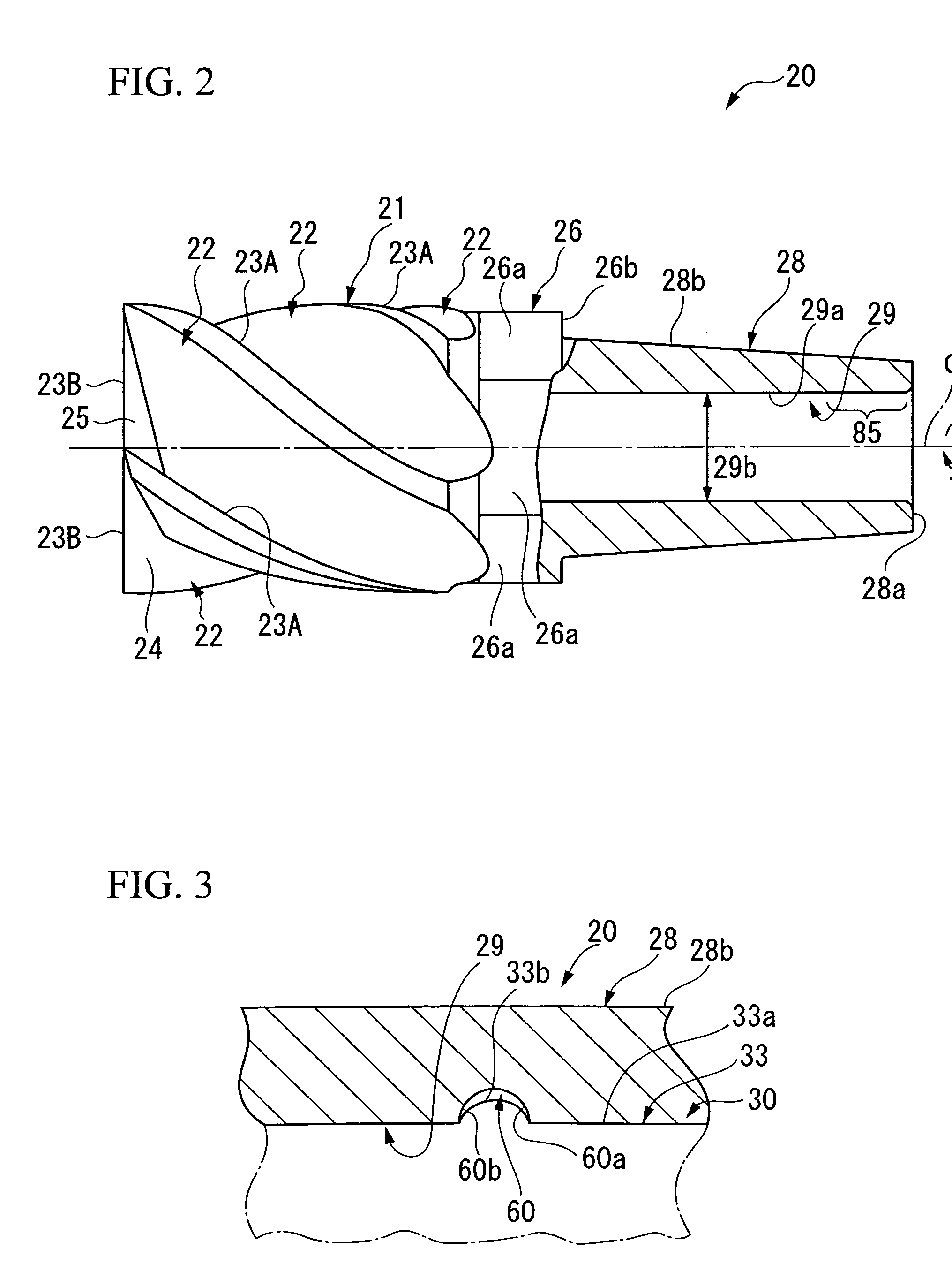
[0323]In the cutting tool 100 of the third embodiment, the engaging hole 29 that opens at the rear-end face 28a of the mounting portion 28 of the cutting head body 110 is not only formed at the inside of the mounting portion 28 but also formed so as to further extend toward the front-end side and reach the inside of the cutting portion 21.

[0324]As a result, since the weight of the cutting head body 110 can be reduced, vibration is prevented from being generated at the cutting portion 21 during a machining process, and it is thereby possible to perform a machining process with a high level of precision.

[0325]As described ab...


PUM

PropertyMeasurementUnit
Angleaaaaaaaaaa
Angleaaaaaaaaaa
Surface roughnessaaaaaaaaaa

Abstract

An exchangeable cutting head that is inserted into a mounting hole formed on a tool body, screwed on a mounting screw section provided on a bottom portion of the mounting hole, and is attached removably to the tool body, the exchangeable cutting head includes: a cutting head body including: a cutting portion provided at a front-end section; a mounting portion provided at a rear-end section and inserted into the mounting hole; and an engaging hole having an inner-peripheral face on which a recessed portion is formed, the cutting head body being made of a hard material; and a connection member including: a shaft portion that is inserted into the engaging hole, includes an outer periphery attached firmly to the inner-peripheral face of the engaging hole, and is engaged with the inner-peripheral face; a head screw section screwed with the mounting screw section; and a hole section formed inside of the head screw section and the shaft portion and along a center line of the shaft portion, the connection member being made of a metal material having a degree of hardness lower than a degree of hardness of the hard material and the connection member being connected to the cutting head body.

Description

BACKGROUND OF THE INVENTION[0001]1. Field of the Invention[0002]The present invention relates to a cutting tool in which an exchangeable cutting head having a cutting portion is attached removably to a tool body.[0003]This application is based on and claims priority from Japanese Patent Application No. 2009-079852, filed on Mar. 27, 2009 and Japanese Patent Application No. 2009-286638, filed on Dec. 17, 2009, the contents of which are incorporated herein by reference.[0004]2. Background Art[0005]Conventionally, a cutting tool in which an exchangeable cutting head is attached removably to a tool body is known.[0006]In the cutting tool having the exchangeable cutting head, the exchangeable cutting head includes a cutting head body having a cutting portion and a connection member that is provided at a rear-end of the cutting head body and has a head screw section.[0007]In addition, the tool body has a mounting hole formed at the tool body and a female screw section formed at the mounti...

Claims


Application Information

Patent Timeline
IPC IPC(8): B23C5/20B23C5/26
CPCB23B31/1107B23B31/1122B23C5/10Y10T407/22B23C2210/03Y10T409/30952B23C2210/02B21K25/00B23C5/20B23C5/22B23C5/26B23Q3/12
Inventor AZEGAMI, TAKAYUKIKIMURA, YOSHIHIKO
Owner MITSUBISHI MATERIALS CORP
Why Eureka
Try Eureka