
System and method for altering the optical properties of a material

a technology of resilient materials and optical properties, applied in the field of devices for altering the optical properties of transparent resilient materials, can solve problems such as the change of forces inside the material, and achieve the effect of maintaining the integrity of the corneal surfa

Inactive Publication Date: 2010-09-30
TECHNOLAS PERFECT VISION
View PDF20 Cites 20 Cited by
  • Summary
  • Abstract
  • Description
  • Claims
  • Application Information

AI Technical Summary

Benefits of technology

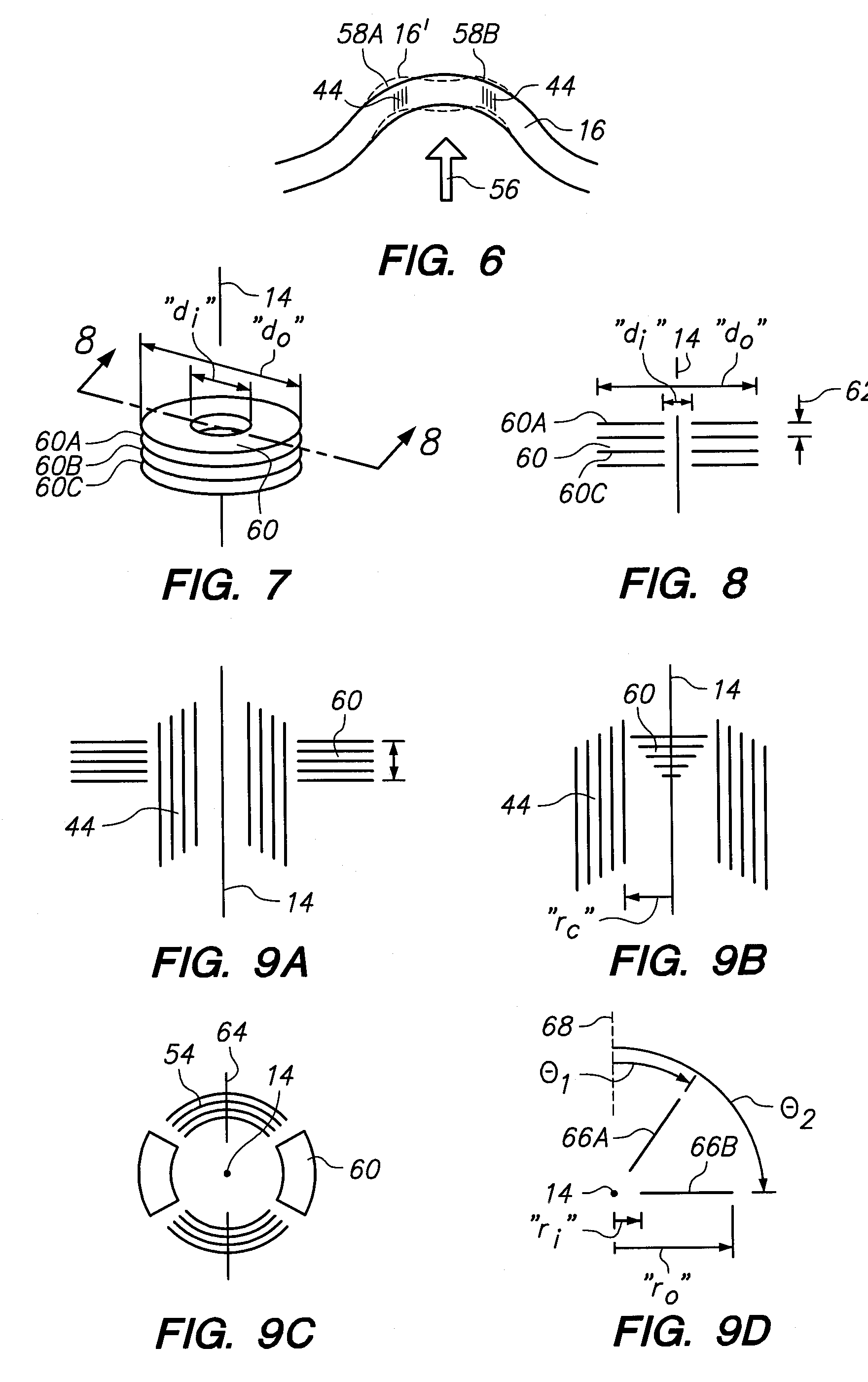
[0016]As intended for the present invention, all “cuts” and “layers” (i.e. the radial cuts, cylindrical cuts, and the annular layers) will weaken stromal tissue, and thereby cause a redistribution of bio-mechanical forces in the stroma. Specifically, weaknesses in the stroma that result from the LIOB of “cuts” and “layers” will respectively cause the stroma to “bulge” or “flatten” in response to the intraocular pressure from the anterior chamber. As noted above, however, these changes will be somewhat restrained by Bowman's capsule. The benefit of this restraint is that the integrity of the cornea is maintained. Note: in areas where layers are created, there can be a rebound of the cornea that eventually results in a slight bulge being formed. Regardless, with proper prior planning, the entire cornea can be bio-mechanically reshaped, as desired.

Problems solved by technology

However, under circumstances where external forces on the material are held constant, it becomes necessary to somehow change forces inside the material.

Method used


Image

  • System and method for altering the optical properties of a material
  • System and method for altering the optical properties of a material
  • System and method for altering the optical properties of a material

Examples


Embodiment Construction

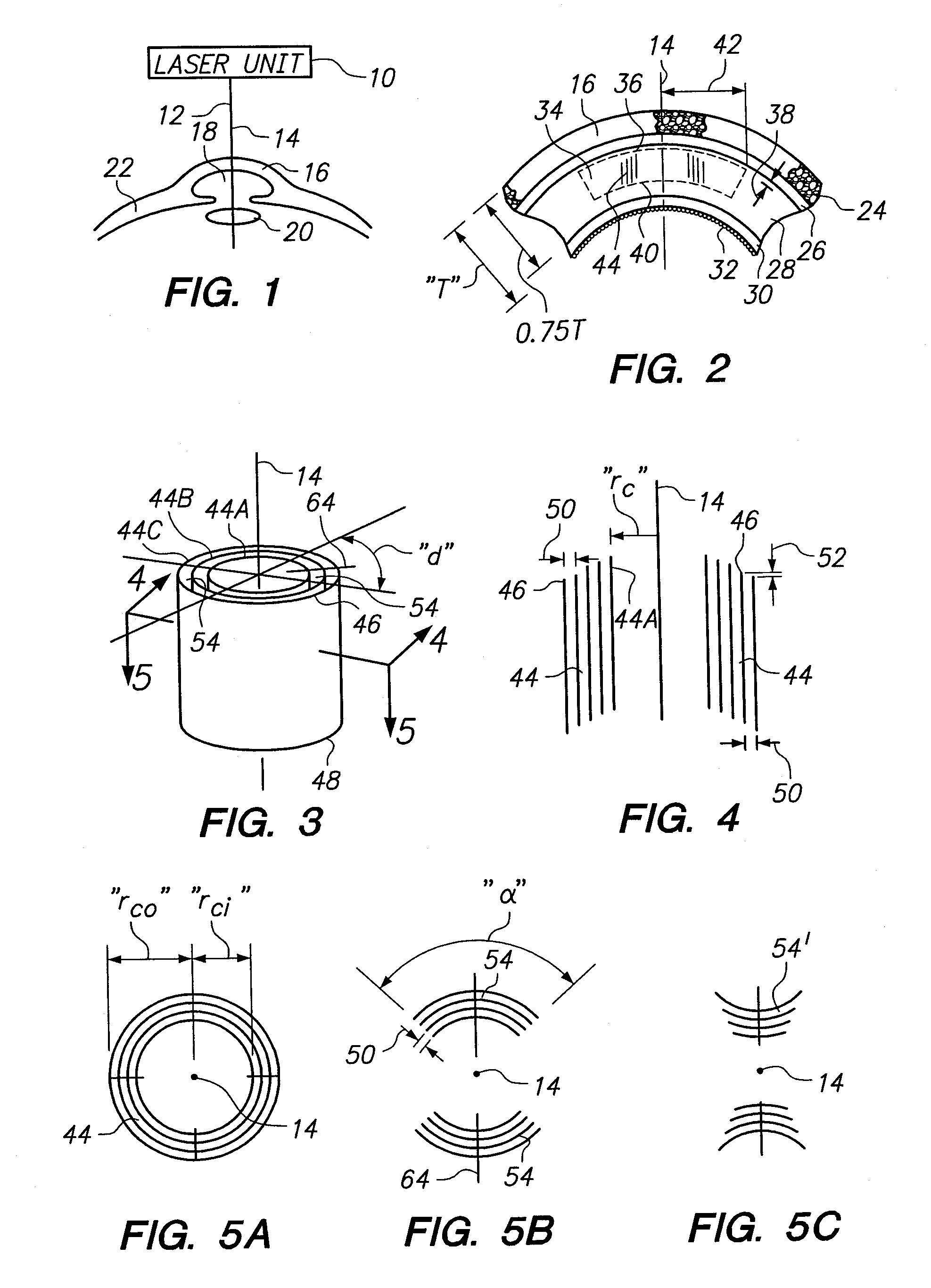
[0053]Referring initially to FIG. 1, it will be seen that the present invention includes a laser unit 10 for generating a laser beam 12. More specifically, the laser beam 12 is preferably a pulsed laser beam, and the laser unit 10 generates pulses for the beam 12 that are less than one picosecond in duration (i.e. they are femtosecond pulses). In FIG. 1, the laser beam 12 is shown being directed along the visual axis 14 and onto the cornea 16 of the eye. Also shown in FIG. 1 is the anterior chamber 18 of the eye that is located immediately posterior to the cornea 16. There is also a lens 20 that is located posterior to both the anterior chamber 18 and the sclera 22.

[0054]In FIG. 2, five (5) different anatomical tissues of the cornea 16 are shown. The first of these, the epithelium 24 defines the anterior surface of the cornea 16. Behind the epithelium 24, and ordered in a posterior direction along the visual axis 14, are Bowman's capsule (membrane) 26, the stroma 28, Descemet's memb...


PUM


Abstract

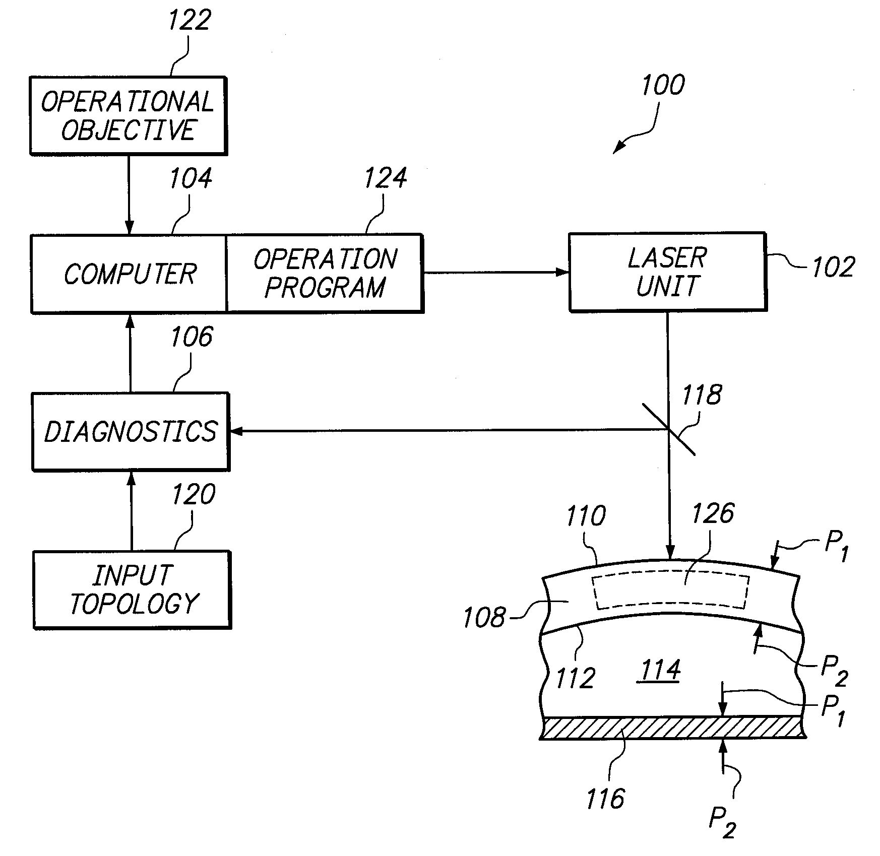
A system for changing the configuration of a transparent, resilient material, for the purpose of altering its optical properties, requires obtaining a topology for the material. The obtained data is then used to create a computer program for operating a laser unit. In accordance with the program, the laser unit creates incisions within a defined operational volume, inside the material, to weaken the material (i.e. change its internal stress distributions). Specifically, the incisions are made on predetermined surfaces (e.g. cylindrical surfaces) in the operational volume by Laser Induced Optical Breakdown (LIOB). As a consequence of the incisions, the material undergoes the desired configurational change in response to external forces applied on the material.

Description

[0001]This application is a continuation-in-part of application Ser. No. 12 / 105,195 filed Apr. 17, 2008, which is currently pending, and which is a continuation-in-part of application Ser. No. 11 / 958,202 filed Dec. 17, 2007, which is currently pending. The contents of application Ser. Nos. 12 / 105,195 and 11 / 958,202 are incorporated herein by reference.FIELD OF THE INVENTION[0002]The present invention pertains generally to devices for altering the optical properties of a transparent resilient material. More particularly, the present invention pertains to devices and systems that change stress distributions within a material to reconfigure the material. The present invention is particularly, but not exclusively, useful as a device and system for changing stress distributions within a material, to reconfigure the material, and to thereby alter its optical properties in response to external forces exerted on the material.BACKGROUND OF THE INVENTION[0003]The cornea of an eye has five (5)...

Claims


Application Information

Patent Timeline
Patent Type & Authority Applications(United States)
IPC IPC(8): A61B18/20
CPCA61F9/008A61F9/00827A61F9/00838A61F2009/00897A61F2009/00882A61F2009/00895A61F2009/00872
Inventor RUIZ, LUIS ANTONIOBILLE, JOSEF F.LOESEL, FRIEDER
Owner TECHNOLAS PERFECT VISION
Learn More