SYSTEM AND METHOD FOR OBTAINING AN OPTIMAL ESTIMATE OF NOx EMISSIONS

a technology of nox emissions and optimal estimation, applied in the direction of exhaust treatment electric control, separation process, instruments, etc., can solve the problems of difficult implementation, complicated pems, and high cost of continuous emissions monitoring systems, and achieve the effect of fast response to signals

Active Publication Date: 2010-10-07
GENERAL ELECTRIC CO
View PDF9 Cites 11 Cited by
  • Summary
  • Abstract
  • Description
  • Claims
  • Application Information

AI Technical Summary

Problems solved by technology

Continuous emissions monitoring systems are quite expensive, particularly due to the installation cost and demanding maintenance and calibration requirements of the gas analyzers.
However, the PEMS are complicated, relatively costly, and difficult to implement.

Method used


Image

  • SYSTEM AND METHOD FOR OBTAINING AN OPTIMAL ESTIMATE OF NOx EMISSIONS
  • SYSTEM AND METHOD FOR OBTAINING AN OPTIMAL ESTIMATE OF NOx EMISSIONS
  • SYSTEM AND METHOD FOR OBTAINING AN OPTIMAL ESTIMATE OF NOx EMISSIONS

Examples


Embodiment Construction

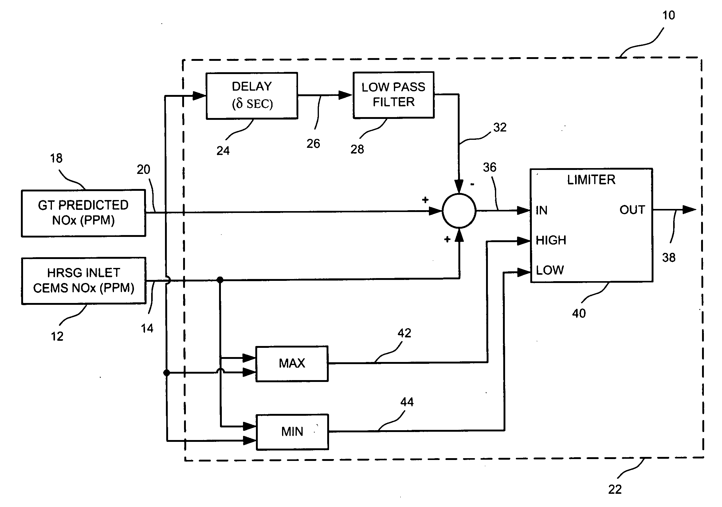
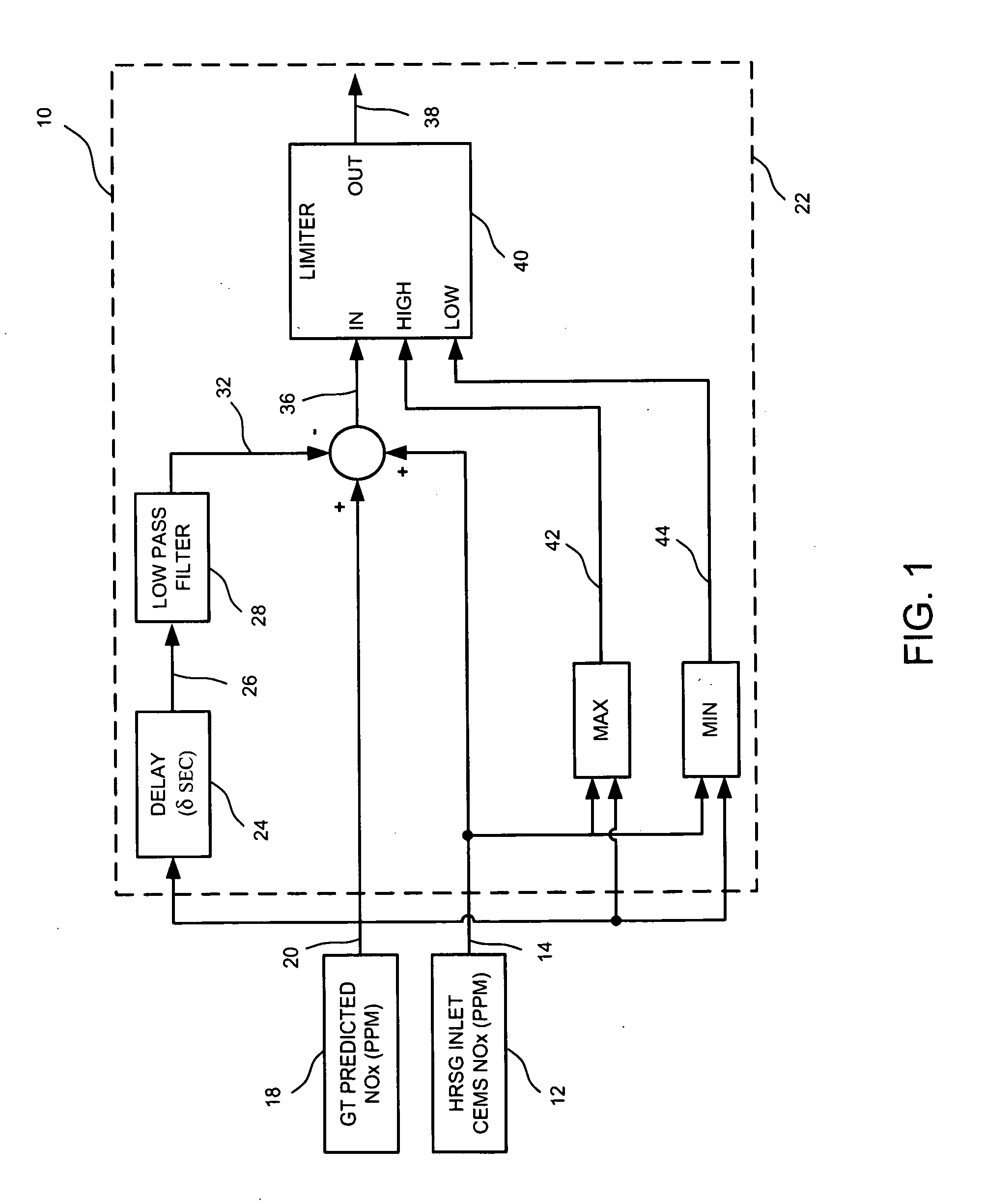
[0015]As discussed in detail below, embodiments of the invention include a system and method for obtaining an optimal estimate of NOx emissions. The system and method include a technique to introduce a time delay in a relatively faster, responsive signal and filter the signal via a low pass filter. As used herein, the term ‘NOx emission’ includes emission of gases such as, but not limited to, nitrogen oxide and nitrogen dioxide.

[0016]FIG. 1 is a schematic illustration of a control system 10 for obtaining an optimal estimate of NOx emissions in an exhaust during a selective catalytic reduction process. The system 10 includes a continuous emission monitoring sensor (CEMS) 12 having a first time constant to generate a responsive signal 14 representing a first estimate of NOx emission. In a particular embodiment, the first time constant includes a range between about 60 seconds to about 180 seconds. The responsive signal 14 has a first time lag between a time of measurement of NOx emiss...


PUM

PropertyMeasurementUnit
timeaaaaaaaaaa
time constantaaaaaaaaaa
time lagaaaaaaaaaa

Abstract

A control system for providing an optimal estimate of NOx emission in an exhaust during a selective catalytic reduction process is provided. The control system includes a continuous emission monitoring sensor configured to generate a responsive signal representing a first estimate of NOx emission; wherein the responsive signal has a first time lag between a time of measurement of NOx emission and the time when the corresponding responsive signal is made available by the continuous emission monitoring sensor, and the continuous emission monitoring sensor has a first time constant. The control system also includes a virtual sensor configured to generate a relatively faster responsive signal representing a second estimate of NOx emission. The control system further includes a processor that includes a time delay compensation circuit configured to introduce a second time lag in the relatively faster responsive signal, wherein the second time lag matches the first time lag. The processor also includes a low pass filter circuit coupled to the time delay compensating circuit, wherein the low pass filter circuit has a second time constant matching the first time constant to generate a time delayed signal representing a third estimate of NOx emission. The processor is further configured to subtract the time delayed signal from the summation of the responsive signal and the relatively faster responsive signal to generate the optimal estimate of the NOx emission, wherein the optimal estimate is fed as a feedforward signal into an injection system in the selective catalytic reduction process.

Description

BACKGROUND[0001]The invention relates generally to systems for monitoring NOx emissions, and more particularly to systems for obtaining an optimal estimate of the emissions.[0002]Public awareness has increased with respect to the environment, and primary pollutants such as nitrogen oxides and sulfur dioxide are currently regulated in most industries. A great deal of attention in recent years has been spent on addressing the monitoring requirements of these regulations, in order to minimize the discharge of noxious gases into the atmosphere by industrial facilities.[0003]One technique for ensuring correct monitoring of NOx has been to implement continuous emissions monitoring systems (CEMS). A CEM system typically includes a gas analyzer installed either directly in the exhaust stack, or connected via an extractive system which extracts a gas sample from the exhaust stack and conveys it to an analyzer at grade level. Continuous emissions monitoring systems are quite expensive, partic...

Claims


Application Information

Patent Timeline
Patent Type & Authority Applications(United States)
IPC IPC(8): F01N11/00F01N3/10
CPCB01D53/30B01D53/8625B01D53/90B01D2251/2062F01N3/208F01N9/005Y02T10/24F01N2900/0411F01N2900/1402F23J15/003G05B13/048G05B17/02Y02T10/47F01N2560/026Y02T10/12Y02T10/40
Inventor MEHENDALE, CHARUDATTA SUBHASHSMITH, GORDON RAYMOND
Owner GENERAL ELECTRIC CO
Why Eureka
Try Eureka