[0038]In this description a processing unit refers to any processing unit suitable for processing materials, such as a feeder, a belt conveyor, a crusher, a screen, or a corresponding device for transferring, refining or sorting material. Processing units used in recycling material, such as shredders and metal separators, belong to this group as well. The material being processed can be mineral material. The mineral material can be ore, broken rock or gravel, various types of recyclable construction waste, such as concrete, bricks or asphalt. The material can also be domestic waste, as well as wood, glass or metal.
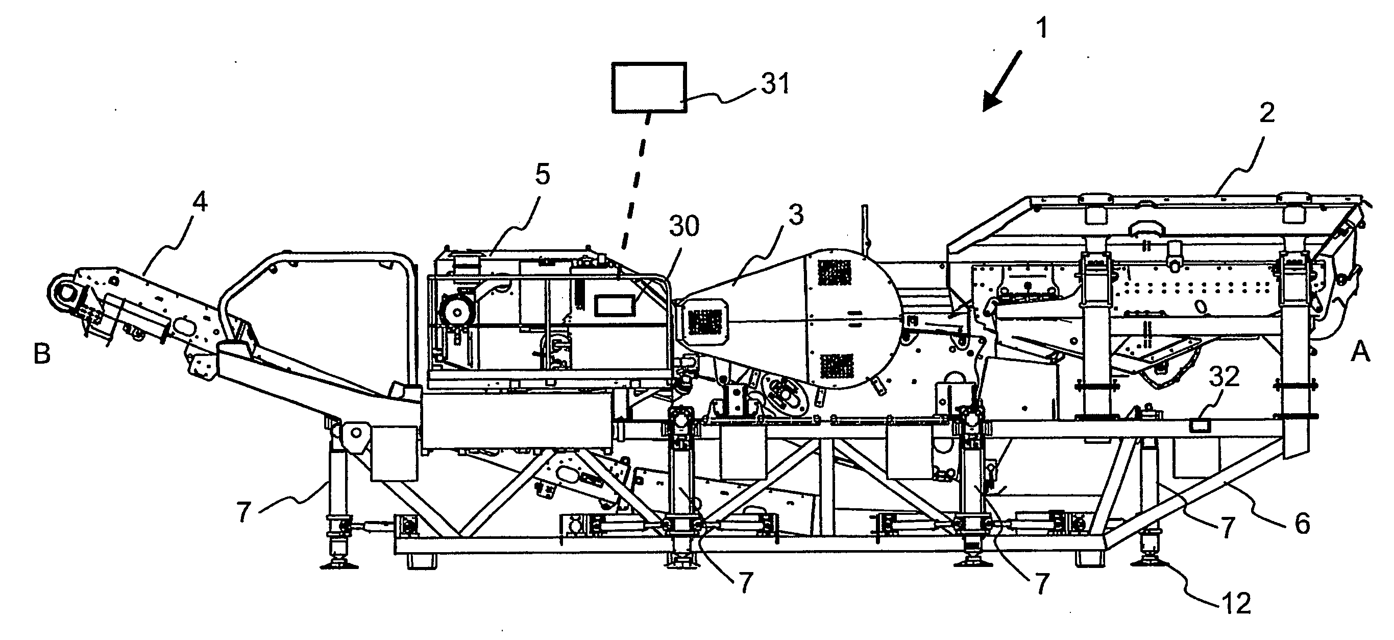
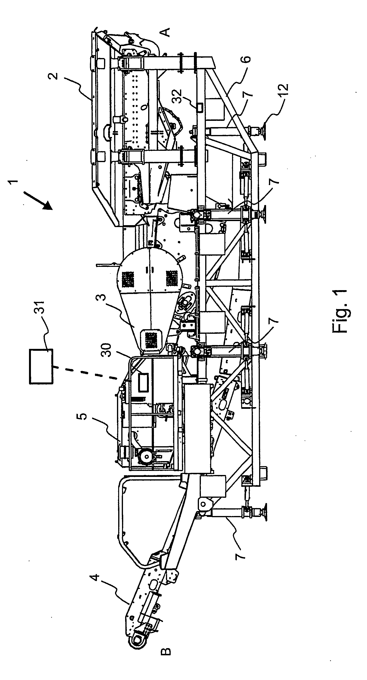
[0039]FIG. 1 shows a processing device 1 for mineral material comprising a feeder 2 for feeding material to a crusher 3 and a belt conveyor 4 for conveying the crushed product further away from the device. The crusher in the figure is a jaw crusher, but other types of crushers, such as a gyratory crusher, a cone crusher or a centrifugal crusher can be placed as parts of the processing device. In addition, the device comprises a power source 5, such as a diesel motor, which produces energy for the use of processing units.
[0040]The feeder, crusher, power source and conveyor are attached to a frame 6. Legs 7 for moving the device are also attached in an articulated manner to the frame 6. In this embodiment there are six legs 7, as is shown in FIG. 2 as well. FIG. 2 shows the processing device from below, without the conveyor belt of the conveyor. The legs 7 are attached to the frame in relation to the center of gravity so that the frame 6 is substantially horizontal when the device is moved. The legs are placed in the frame 6 in relation to the processing device 1 so that one leg is in the front end A of the device, i.e. below the feeder 2, and one leg is in the back end B of the device, i.e. below the conveyor 4. The remaining four legs are placed on both sides of the frame in pairs so that the legs on opposite sides of the frame are at the same point in relation to the length of the frame. As can be seen in FIGS. 1 and 2, the legs 7 attached on the long sides 6a and 6b of the frame are attached on the outside of the frame. In an embodiment of FIG. 1 the processing device 1 is shown in a working position, where the frame is lowered onto a base, i.e. on the ground and the support plates 12 of the legs 7 have also been taken to the ground to support the device. In addition, the device comprises a control unit 30, whose operation is described more in detail later.
[0041]When placing the legs onto the frame, it must be taken into account that the processing devices, for example side conveyors (not shown in the figures) can be attached to the frame. In addition, it must be taken into account that the legs are around the center of gravity. In addition, from the point of view of movement it is important that the stability marginal located around the center of gravity of the device is as wide as possible. The stability marginal describes an imaginary planar surface, inside which the center of gravity of the processing plant may vary during movement in order to keep the device in balance and to prevent it from falling over. FIGS. 3a and 3b show schematically the different possibilities of placing legs 7 in a device and the stability marginals 8 created on the basis of that. FIG. 3a shows the placement of legs 7 according to FIGS. 1 and 2. As can be seen from the figure, with this placement a large stability marginal 8 around the center of gravity 9 is created. This increases the efficiency of movement of the device, especially when moving sideways. The stability marginal is especially increased by the placement of one leg at both the front end A and the back end B of the device in order to receive the load weights caused there. FIG. 3b shows another embodiment where the legs 7 are placed in pairs on both sides of the device 1 so that the legs on opposite sides of the frame are at the same point in relation to the length of the device. The stability marginal of this alternative is not as large as in the embodiment of FIG. 3a. It is, however, enough for moving the device from one location to another without the danger of losing the balance of the device.
[0042]When transferring the processing device a part of the legs is always in a support stage, i.e. touching the ground, and a part in a transfer phase, i.e. off the ground and moving towards a new position. The predefined plan that defines how many legs are in the support and transfer phases is called a walking mode. For example, the possible walking modes of a processing device comprising six legs are a 5/6 mode, a 4/6 mode and a 3/6 mode. The first number refers to the number of legs in the support phase and the second number to the total number of legs. Thus, in the 5/6 mode the device comprises six legs, five of which are in the support phase, i.e. only one leg at a time is off the ground and moving towards a new position. In the 4/6, mode four legs are in the support phase and two legs in the transfer phase. Correspondingly, in the 3/6 mode three legs are in the support phase and three legs in the transfer phase. The greatest speed of moving is reached by this walking mode. If at least two legs are in the transfer phase, the movement of the legs can take place at different times with respect to each other, or the movement can be simultaneous. For example, the legs can move simultaneously in pairs. However, there must always be at least three legs in the support phase. Support and transfer phases follow each other at each leg. The legs in the support phase not only keep the device in balance, but also move the frame of the device to the desired direction. The legs in the transfer phase move in the air according to a path and direction of movement defined for them, until they are again lowered to the ground and they transfer to the support phase. During movement the legs are moved according to the selected walking mode. The selection of the walking mode is primarily affected by the difficulty of the terrain, but also the number of legs and the desired speed of movement. The movement and the alternation of the support and transfer phases of the legs are described more in detail in connection with FIGS. 8a to 8d.
[0043]The processing device can be transferred to various directions. FIGS. 4a to 4f show some examples of the directions of movement of the processing device. The processing device 1 can naturally be transferred forward, in the direction of arrow D1, and backward, in the direction of arrow D2, as shown in FIG. 4a. Transfer in both side directions is also possible. This is shown by arrows D3 and D4. Transfer of the device forward and backward in the direction of its corners is shown by arrows D5, D6, D7 and D8. It is also possible to transfer the device 1 so that the device moves in the desired direction and it is turned at the same time, as shown in FIG. 4b. The direction of movement is shown by arrow D9 and the new position of the device is shown by dashed lines. FIG. 4c shows the direction of movement, where the device moves to the desired direction so that the frame is not turned, but it is kept in the starting direction the entire time. This walking can also be called crab walking. The direction of movement is indicated with arrow D10. Transfer according to FIGS. 4b and 4c can take place in all directions shown in FIG. 4a.
[0044]The processing device 1 can also be transferred or its position can be changed by turning it freely around a selected point. The freely selectable point 34 can be located anywhere inside or outside the bottom area of the device. It can be, for example, the center of the device, around which the device is turned. This is illustrated by arrows D11 in the FIG. 4d. In FIG. 4e a freely selectable point 34 is placed inside the bottom area of the device 1 and the possible turning directions of the device are illustrated by arrows D12. The freely selectable point 34 can also be placed outside the device, as is shown in FIG. 4f. The arrows D13 show the turning directions of the device. All the above-presented directions of movement and turning alternatives can naturally be combined as desired.
[0045]FIG. 5 shows a leg 7. This type of legs are also arranged in the processing device shown in FIGS. 1 and 2. The leg 7 comprises three transfer members 10, 14 and 15, which are rigid in relation to their longitudinal axis. In this embodiment the transfer members are hydraulic cylinders, but other longitudinally adjustable transfer members can also be used. The longitudinal movement can be created, for example, with a worm screw and an electric motor. This kind of an arrangement is called an electric cylinder as well.
[0046]The first hydraulic cylinder 10 is vertically attached in an articulated manner to the frame of the processing device. It is possible to adjust the length of the leg by means of it. It also carries the vertical forces and the weight of the processing device when the processing device is moved or when the leg acts as a support leg when using the device. In the figure the first hydraulic cylinder 10 is shown in a position where a part of a transfer arm 11a of the cylinder is outside a cylinder chamber 11. A support plate 12 is attached to the lower end of the transfer arm. 11a of the first cylinder 10, the lower surface of which plate, i.e. a support surface 13 touches the ground when the leg 7 is in the support phase. The support surface 13 can have, for example, a square-like shape with side lengths of 350 mm×350 mm. The area of the support surface is dimensioned according to the type of base of the working site. The weight of the processing device is also taken into account in the dimensioning. The support plate 12 is attached to the end of the transfer arm of the first hydraulic cylinder with a fastening means 12a, which enables the tilting of the support plate in relation to the transfer arm. For example, a ball joint can be used as the fastening means. The first cylinder is articulated to the frame 6 of the processing device by means of a first articulation 20 and a second articulation 21 arranged in the upper end of the cylinder chamber 11. The second and third hydraulic cylinder 14 and 15 are articulated to the first hydraulic cylinder 10 substantially horizontally and on the same level with each other. The transfer arms 16 and 17 of the second hydraulic cylinder 14 and the third hydraulic cylinder 15 are attached by means of a third articulation 22 and a fourth articulation 23 to the lower part of the cylinder chamber 11 of the first hydraulic cylinder, within a distance from the lower end of the cylinder chamber. Their ends on the side of the cylinder chamber 18 and 19 are, in turn, articulated to the frame 6 of the processing plant by means of a fifth articulation 24 and a sixth articulation 25. The second and third hydraulic cylinder 14, 15 create the sideways movements of the leg 7. The movement of the leg 7 created by the hydraulic cylinders 14 and 15 comprises both a horizontal and a vertical component, whose size, varies depending on the desired path of movement of the leg. In other words, the path of movement of the support plate 12 can be arch-like or take place only on the horizontal plane. The first hydraulic cylinder 10 is larger in size and in its cylinder capacity than the second and third hydraulic cylinder 14 and 15.
[0047]Measuring means, i.e. sensors, are arranged in the leg 7, for defining the position of the leg and the position of the support plate 12 substantially continuously. In connection with the first hydraulic cylinder, in its upper end, or, for example, inside articulations 20 and 21 are arranged first measuring means, i.e. two angle sensors 26 and 27, with which the angle position of the hydraulic cylinder 10 in relation to the frame 6 is measured. In addition, a second measuring means 28, such as a linear sensor for measuring the vertical position of the support plate 12 in relation to the frame, is arranged in the first cylinder. Thus, the linear sensor measures the magnitude of the vertical movement of the first cylinder 10. For example, a magnetostrictive sensor can be used as a linear sensor. The second measuring means can also be an optical measuring means, such as a measuring device based on a laser or image processing. In addition, measuring devices based on acoustic methods as well as magnetic field measuring, such as an ultrasound sensor or an eddy current sensor, can be used. With these three sensors 26, 27 and 28 the position of the support plate 12 in relation to the frame can be defined.
[0048]Measuring means 38 and 39 arranged in the hydraulic cylinders 14 and 15 can also function as first measuring means, which may have the same measuring principle as the above-mentioned measuring means 28. By means of them the length of at least one of the hydraulic cylinders 14 and/or 15 is measured, from which length it is possible to determine the angle position of the hydraulic cylinder 10 and further the position of the support plate 12 in relation to the frame.
[0049]The pressure prevailing in the cylinder chamber of the first hydraulic cylinder 10 is measured as well. The measurement takes place by means of a pressure sensor 29. On the basis of pressure measurements it is possible to determine the pressure caused by the support plate 12 against the base and to ensure that the force the support plate 12 touches the ground with is sufficient. The sensors perform measurements substantially continuously and by means of the measurements the position of the support plate 12 in both the transfer and support phases can be determined continuously. In addition, the position of the frame in relation to the base is measured with an inclination sensor 32. The inclination sensor can be, for example, an inclinometer. The measuring signals measured by the sensors are sent to a control unit 30 placed in the processing device. The control unit 30 controls the movement of the processing device according to commands provided by the user of the processing device, which commands are sent to the control unit 30 with a user interface 31 connected to it. The user interface can be, for example, a joy-stick-type interface based on wireless signal transfer, or a keyboard. Thus, a transmitter is arranged in the user interface for transmitting control commands to the control unit, and a receiver is arranged in the control unit for receiving them. In the figure the wireless data transfer is illustrated by a dashed line. In addition, the user interface 31 may be connected to the control unit 30 by a cable.
[0050]The measurement signals measured by the measuring means, i.e. the angle sensors 26 and 27, the linear sensor 28, the pressure sensor 29 and the inclination sensor 32, can be directed to the control unit 30 either via cables or wirelessly. If the measurements are transmitted to the control unit wirelessly, the measuring means are provided with a transmitter for transmitting measurement results, and the control unit is provided with a receiver for receiving measurement signals. The control unit forms control commands for moving the hydraulic cylinders of the legs on the basis of the measurement signals and other control parameters. The control commands produced by the control unit can also be conveyed to the legs either via cables or wirelessly. If the control commands are transmitted to the legs wirelessly, such as via radio waves or infrared radiation, the control unit is provided with a transmitter for transmitting control commands and the legs are provided with a receiver for receiving control commands.
[0051]The control unit 30 comprises means for performing the operations of the method according to the invention. FIG. 7 shows more closely a control unit 30, which includes means 33 to 35 for calculating and determining the parameters necessary for moving the process device, as well as for determining the control signals. The steps of the above-described method can be performed by a program, for example by a micro processor. The means may be composed of one or more microprocessors and the application software contained therein. In this example, there are several means, but the different steps of the method can also be performed in a single means.
[0052]The control unit 30 comprises calculating means 33, which receive the data concerning the desired walking mode and the direction and speed of movement of the processing device sent by the user of the processing device. The calculating means 33 also receive the measurement signals measured by the measuring means 26, 27, 28, 29 and 32 and on the basis of them and the selected walking mode they calculate a step diagram for each leg 7 and on the basis of that determine their next path and direction of movement. Determining the path and direction of movement of the legs also takes into account the so-called step box, i.e. a cubic capacity in square space, where the support plate 12 can move within the limits set by the cylinders.
[0053]The paths and directions of movement determined for each leg by the calculating means 33 are transmitted to control signal formation means 35 in the control unit, which means form control commands for each hydraulic cylinder 10, 14 and 15 of each leg 7. After this, the control commands are sent to the valves (not shown in the figure) controlling the hydraulic cylinders 10, 14 and 15.
[0054]The means 33 and 35 contained by the control unit perform the procedures designated for them continuously while the processing device moves. The control unit receives data from the measuring means on the position of each support plate in relation to the frame and continuously controls the movement of all legs according to the selected walking mode so that the targets for the direction of movement set by the controller of the device are realized. The processing of measurement signals can be performed in a centralized manner with one control unit.
[0055]As was stated above, the control unit 30 comprises means for controlling the movement of the legs. The control unit may also comprise means for controlling the process itself, such as the operation of a crusher, conveyor or the like.
[0056]FIG. 6 shows the leg 7 of FIG. 5 in a basic position seen from above. As can be seen in the figure, the second and third hydraulic cylinders 14 and 15 are attached to the first hydraulic cylinder 10 so that an angle α is formed between them. The size of the angle α depends on several factors, for example, on the fastening point of the cylinders 14 and 15 to the frame 6, the dimensions of the processing device, the length of the cylinders 14 and 15, and the diameter of their cylinder chambers, as well as the required horizontal powers. These factors are selected so that the desired step box is created.
[0057]When taking a step, the hydraulic cylinders of the leg in the transfer phase operate in the following manner: first, the support plate 12 of the leg is lifted off the ground by means of the first cylinder 10, by pulling the transfer arm 11a of the first cylinder inside the first cylinder chamber 11. How high the support plate 12 of the leg is lifted depends on the desired height of the step. After this the second and/or third cylinder 14 and 15 move the first cylinder 10 to the desired direction by pushing and/or pulling the transfer arms 16 and 17 of the cylinders from the cylinder chambers/to the cylinder chambers 18 and 19, until the desired direction of the step is reached. Finally, the first hydraulic cylinder lowers the support plate 12 of the leg back to the ground by pushing the transfer arm 11a of the first cylinder outwards from the first cylinder chamber. Naturally the operations of the first hydraulic cylinder and the second and/or third hydraulic cylinder can take place simultaneously as well. The legs in the support phase move the frame of the processing device towards the desired direction continuously; it is not lowered to the ground between steps. The length of the step, and at the same time the transfer speed of the device is controlled with the control system.
[0058]The movement and the alternation of the support and transfer phases of the legs are described more in detail in connection with FIGS. 8a to 8d. For clarity, the processing device is not shown in the figure. Six legs 7 are attached to the frame and the movement takes place in a 3/6 walking mode. In FIG. 8a the device is shown in the starting position, where all the legs are on the base S, i.e. on the ground.
[0059]In FIG. 8b a part of the legs, i.e. the legs 7A in the transfer phase are lifted off the ground. The legs 7B in the support phase are still on the ground. The desired direction of movement is indicated with the arrow M.
[0060]Next, the legs 7A in the transfer phase are tilted in the air against the direction of movement and moved towards the ground. Simultaneously the legs 7B in the support phase move the frame 6 in the determined direction of movement, which is marked with the arrow M. FIG. 8c shows the phase where the support plates 12 of the legs 7A have already reached the ground.
[0061]When the supporting plates 12 of the legs 7A have again been lowered to the ground and it has been ensured that the device is in balance, the legs 7A transfer to the support phase and the legs 7B that were previously in the support phase transfer to the transfer phase. Thus, two things take place simultaneously: the legs 7A are straightened to a position perpendicular to the surface of the ground and are tilted towards the direction of movement, simultaneously moving the device towards the direction of movement. At the same time the legs 7B begin to rise, straighten and further tilt and lower to the opposite side, i.e. against the direction of movement. The above-presented phases 8b to 8d follow each other until the desired new position of the processing device is reached.
[0062]The user of the processing device can, if desired, change the direction and speed of movement of the device while the processing device is moving. Thus; if necessary, the control unit calculates new control commands according to the new, desired direction.
[0063]As disclosed above, the processing device for mineral material comprises a frame and at least one processing unit, for example, a feeder, a belt conveyor, a crusher or a screen. It is also possible to use a device combination in processing material, which combination comprises several transferable processing devices. This kind of a combination could be, for example, a separate device composed of a feeder, a crusher and a conveyor, as well as a separate device composed of a screen and conveyors, which are placed in relation to each other so that the crushed material from the crusher is fed directly to the screen. Both these processing devices can be equipped with legs and they can be moved in the working site from one place to another as one entity. Thus, control means for moving several processing devices at the same time and to the same direction are formed in the control unit. This can be implemented, for example, so that the coordinates of different processing devices are locked to each other so that by controlling one processing device the other one will follow in the same manner. The location of the devices in the working site is transmitted to the control unit by entering the location data of one device and then positioning the devices in relation to each other. The location of the devices can also be determined with a positioning system, such as a GPS system. Both devices can naturally be moved independently as well. In that case both units must have separate control means.
[0064]Legs can be used not only for transferring the processing device, but also for supporting it during a work phase. In FIG. 1 the processing device is shown in a working position, where the device is lowered to the ground supported by the frame. The legs are also in contact with the ground, in which case they support the device. If there are potholes in the base, the length of the legs is adjusted so that the device is in balance.
[0065]The frame 6, to which the legs 7 are attached, can also be utilized in moving such processing devices or units that do not themselves comprise means for moving the device, such as tracks or wheels. Such a frame is disclosed, for example, in FIGS. 8a to 8d. The frame 6 is brought next to the processing device by means of the legs 7, after which the processing device is moved onto the frame and attached to it. After this the combination of the frame and processing device is moved to the desired position in the working site and the processing device is again detached from the frame and lowered to the ground. Then, the control unit is placed in the frame.
[0066]The invention is not intended to be limited to the embodiments presented as examples above, but the invention is intended to be applied widely within the scope of the inventive idea as defined in the appended claims.