Seal for oil-free rotary displacement compressor

a compressor and oil-free technology, applied in the direction of engine seals, mechanical devices, engine components, etc., can solve the problems of oil used for lubricating the journaling rotor bearing entering the compression space, and affecting the service life of the compressor

Inactive Publication Date: 2010-10-07
ERGOSEAL
View PDF54 Cites 40 Cited by
  • Summary
  • Abstract
  • Description
  • Claims
  • Application Information

AI Technical Summary

Benefits of technology

[0013]Accordingly, what is described herein and claimed below is a shaft seal cartridge for use in rotary displacement compressor, the compressor having a compressor chamber between two shaft bearings, comprising a cartridge carrier deposed in a seal cavity and annularly around a shaft capable of housing at least two self aligning seal rings, the cartridge carrier including a fluid communication path in fluid communication with the environment outside the seal cavity, a first oil seal ring disposed within a cartridge cavity at least partially defined by an inner diameter of said cartridge carrier and sealing between a fluid communication path side and a shaft bearing side, the first oil seal ring being statically sealed against a surface of said cartridge carrier, the first oil seal ring further comprising a spiral groove in an inner diameter surface thereof, and the spiral g

Problems solved by technology

Beyond the complexity and expense of such a device, the oil seal was a “wet seal” in which the gas being compressed, referred to as the process gas, came into contact with the lubricating oil and some became entrained in the process gas resulting in an undesirable condition.
Nevertheless, the risk of oil used for lubricating the journaling rotor bearings entering the compression space remains, and after entering the compressor portion, the high rotational speed of the rotors causes any lubricating oil to mist up and to become entrained in the gas being compressed.
This is highly undesirable when clean “dry” compressed gas is needed.
Other prior art attempts directed toward providing for oil shield integrity and effectiveness have not been completely successful in that the design of the oil shield and sealing methods are cumbersome and complicated and do not always effectively repel oil form reaching the compression space or chamber.
However, because of the need to have the pressure at a high level in order to provide a sufficient barrier to oil leakage, too much of the compressed gas is evacuated from the compression chamber and permitted to leak outwardl

Method used


Image

  • Seal for oil-free rotary displacement compressor
  • Seal for oil-free rotary displacement compressor
  • Seal for oil-free rotary displacement compressor

Examples


second embodiment

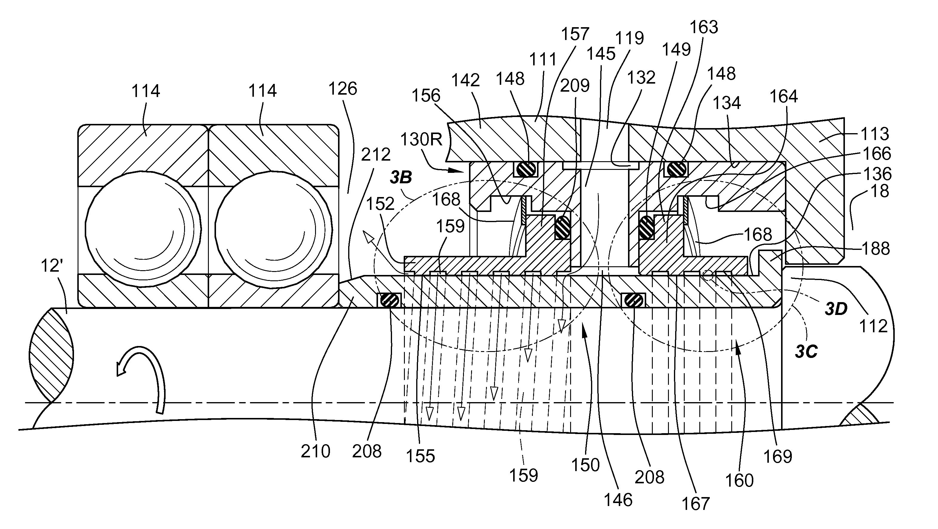
[0054]Referring now to FIG. 3A, the inventive high pressure gas seal cartridge 130R is shown. As can be seen from FIG. 3A, the seal cartridge 130R is on the opposite side from the compression chamber housing the rotors 20, 22 (FIG. 1), than the cartridge 30L described above with reference to FIG. 2. Since some of the elements are the same for both the seal cartridges 30L and 130R, similar identification numbers are used for similar parts, the identification numbers in the embodiment of cartridge 130L in FIG. 3A having a 100 series prefix. For example, instead of a single bearing for the shaft 12′, there are dual bearings 114 that provide radial bearings to support the shaft 12′, as shown to the left of the seal cartridge 130L. Ball bearings 114 provide a smooth bearing of the load of shaft 12′ and limit the amount of eccentric “wobble” of the shaft 12′ relative to the housing 111 into which the cartridge 130R is inserted. Housing 11 also includes one or more fluid communication pass...

first embodiment

[0058]Shaft sleeve 210 rotates with the shaft 12′ and is sealed against the surface thereof by one or more O-rings, two O-rings 208 being shown in FIG. 3A. The cartridge carrier 142 is disposed around the sleeve 210 and houses at least two seal rings, the oil seal ring 152 and the air seal ring 164. Additional rings, either within an expanded version of the carrier, or outside the carrier 142, as in the first embodiment shown in FIG. 2, can be included, but these are not shown for purposes of clarity and economy. For example, in higher-pressure applications, multiple air rings may be used to distribute the pressure drop and provide a more effective leakage barrier against the leakage of process fluid form the compression chamber.

[0059]Shaft sleeve 210 has at one end disposed an upturned circumferential flange 188, which abuts an indented larger diameter portion 112 of shaft 12′ acting as a stop so as to inhibit further movement in the axial direction of the shaft sleeve in the axial...


PUM


Abstract

Non-contacting cartridge shaft seals prevent leakage loss of process gases in an “oil free” rotary screw compressor or blower, while simultaneously preventing ingress of lubricating oil to the pumping chamber, allowing the compressor/blower to generate process pressure differentials without oil contamination. A compact unitized seal cartridge assembly is provided in the end plates of the pump housing. One of the rotor shafts extends through an aperture in the end plate or housing, between the pumping chamber and oil-lubricated gear/bearing cases. Internal elements have the ability to self-align radially achieving essential concentricity with shaft rotational axes. The rotor shafts or sleeves non-contact relationship during operation allow increased ranges of shaft rotational speeds. Air seal elements restrict flow of process air from the pumping or compression chamber, and oil seal elements with a directional spiral groove on the inside diameter prevent the leakage of lubricating oil to the process or atmosphere.

Description

BACKGROUND OF THE INVENTION[0001]1. Field of the Invention[0002]This invention relates generally to dry rotary positive displacement compressors and blowers and in particular to screw compressors using oil for lubrication and cooling to produce oil-free compressed gases, and wherein the compression space produces oil-free compressed gases.[0003]2. Background Art[0004]Rotary displacement compressors include sets of rotary gear wheels and bearings that must be maintained lubricated and cool in order to provide the compressive power while maintaining their integrity. In some prior art devices, for example those described in U.S. Pat. No. 3,976,165 to Pilarczyk, high pressure oil was used to lubricate carbon seal rings in a contacting labyrinth gas seal. Beyond the complexity and expense of such a device, the oil seal was a “wet seal” in which the gas being compressed, referred to as the process gas, came into contact with the lubricating oil and some became entrained in the process gas...

Claims


Application Information

Patent Timeline
IPC IPC(8): F16J15/32
CPCF16J15/406F16J15/164
Inventor LIARAKOS, NICHOLAS P.HILARIS, JOHN A.
Owner ERGOSEAL
Why Eureka
Try Eureka