Quick-connect tube fitting connection including a safety ring

a technology of safety rings and pipe fittings, applied in the direction of couplings, pipe elements, washing machines, etc., can solve problems such as easy breakag

Inactive Publication Date: 2010-10-07
LEGRIS
View PDF9 Cites 40 Cited by
  • Summary
  • Abstract
  • Description
  • Claims
  • Application Information

AI Technical Summary

Benefits of technology

[0013]Once the snap-fastener means have been engaged, it is advantageous for the peripheral link that constitutes the mechanically weakened portion of the ring to be under tension.

Problems solved by technology

The portion having low tensile strength of the link or of the ring when the link is looped constitutes a zone of weakness where it is easy to break the ring if it is desired to enable the pusher to slide so as to release the teeth.

Method used


Image

  • Quick-connect tube fitting connection including a safety ring
  • Quick-connect tube fitting connection including a safety ring
  • Quick-connect tube fitting connection including a safety ring

Examples


Embodiment Construction

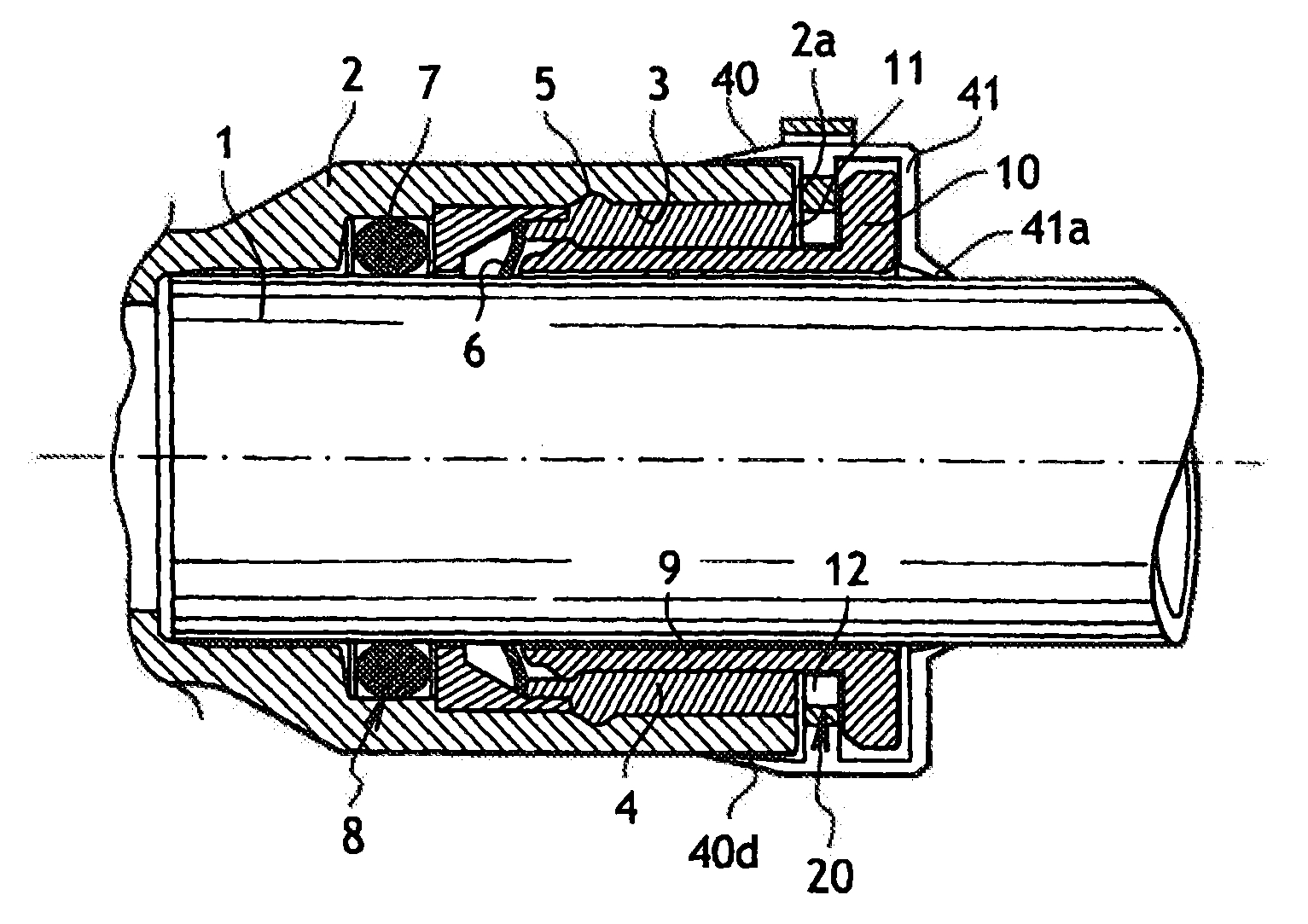
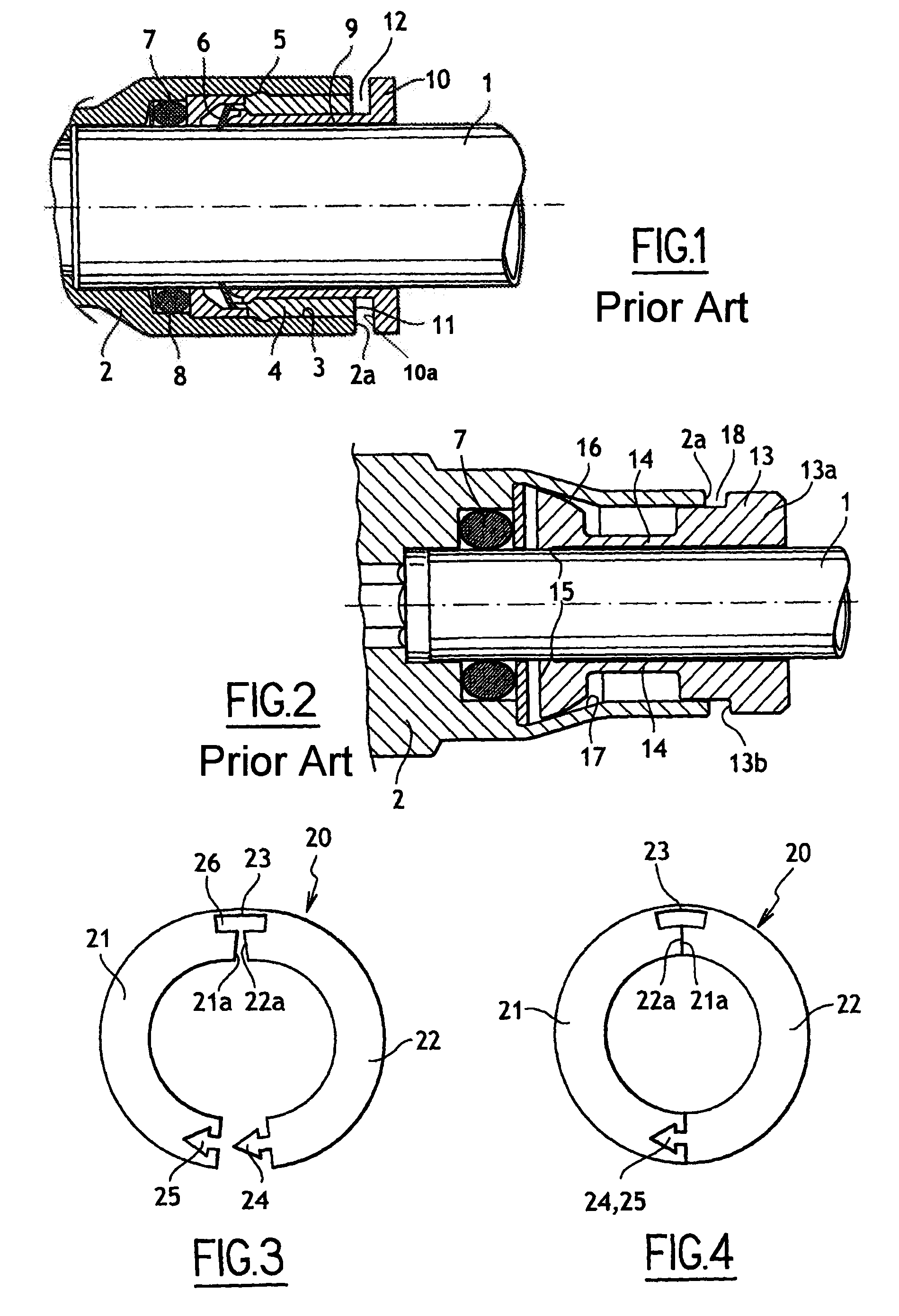
[0026]FIG. 1 shows a quick-coupling device for coupling a tube 1 to a rigid element 2 possessing a bore 3 in which a tubular insert 4 is housed, the insert being held in the bore by means 5 on the outside of its anchoring in the bore.

[0027]The tubular insert includes a toothed washer 6 and a sealing ring 7 is located at the tip of the insert in a recess 8 extending the bore 3. Means are provided inside the insert 4 for the purpose of releasing retention of the tube 1, which means comprise a pusher 9 mounted to move in translation inside the tubular insert 4 to release the retaining means and thus lift the teeth of the washer 6 outwards on being pushed into the tubular insert 4. The release pusher 9 possesses a rear portion or head 10 that projects outside the tubular insert 4 or the rigid element 2 and that presents a shoulder surface 10a situated facing a stationary surface 2a of the stationary element 11 or of the tubular insert, the two surfaces in the example being made to lie i...


PUM

PropertyMeasurementUnit
tensile strengthaaaaaaaaaa
tensionaaaaaaaaaa
axial movementaaaaaaaaaa

Abstract

A quick-coupling tube fitting for coupling a tube to a body having a bore. The fitting includes a retaining member received within the bore for retaining the tube, and a release member received within the bore to be slidably moveable to release the retaining member when pushed. The release member has a rear portion that projects outwardly from the body. The rear portion has a shoulder surface which faces a stationary surface of the body to define a groove therebetween in which a safety member is disposed to delimit the sliding of the release member. The safety member is provided in the form of an elongate member which is closable to form a ring in the groove.

Description

CROSS-REFERENCE TO RELATED APPLICATIONS[0001]This application is continuation of co-pending International Application No. PCT / FR2008 / 001565 filed Nov. 6, 2008, which designated the United States, and which claims priority to French Patent Application 0708010, filed Nov. 15, 2007, the disclosure of each of which is expressly incorporated herein by reference.BACKGROUND OF THE INVENTION[0002]The present invention relates to a quick-coupling device for coupling a tube with a rigid element (e.g. a body of a pneumatic component such as a distributor, an actuator, etc.), and more particularly it relates to a quick-coupling device designed for anchoring a tube in a bore of the rigid element and for sealing the resulting coupling merely by pushing the tube into the bore that is fitted with the coupling device.[0003]Quick-coupling devices of the cartridge type are known that serve to provide a leaktight connection of a tube in a bore of a rigid element, such a device being in the form of a tu...

Claims


Application Information

Patent Timeline
Patent Type & Authority Applications(United States)
IPC IPC(8): F16L25/00B23P17/04
CPCF16B43/006F16L37/091Y10T29/49826F16L37/0982F16L2201/10F16L37/092F16L2201/80F16L37/0915F16L37/0927
Inventor LE QUERE, PHILIPPE
Owner LEGRIS
Why Eureka
Try Eureka