

Passive harmonic-rejection mixer
a mixer and harmonic-rejection technology, which is applied in the direction of instruments, electric/magnetic computing, computation using denominational number representation, etc., can solve the problems of affecting the rejection of the third and fifth harmonics of the oscillator signal, the difficulty of passing hr mixer implementation, and the inability to realize the effect of the third harmonic and the fifth harmonic, so as to reduce the influence and the input impedance
- Summary
- Abstract
- Description
- Claims
- Application Information
AI Technical Summary
Benefits of technology
Problems solved by technology
Method used
Image

Examples
first embodiment
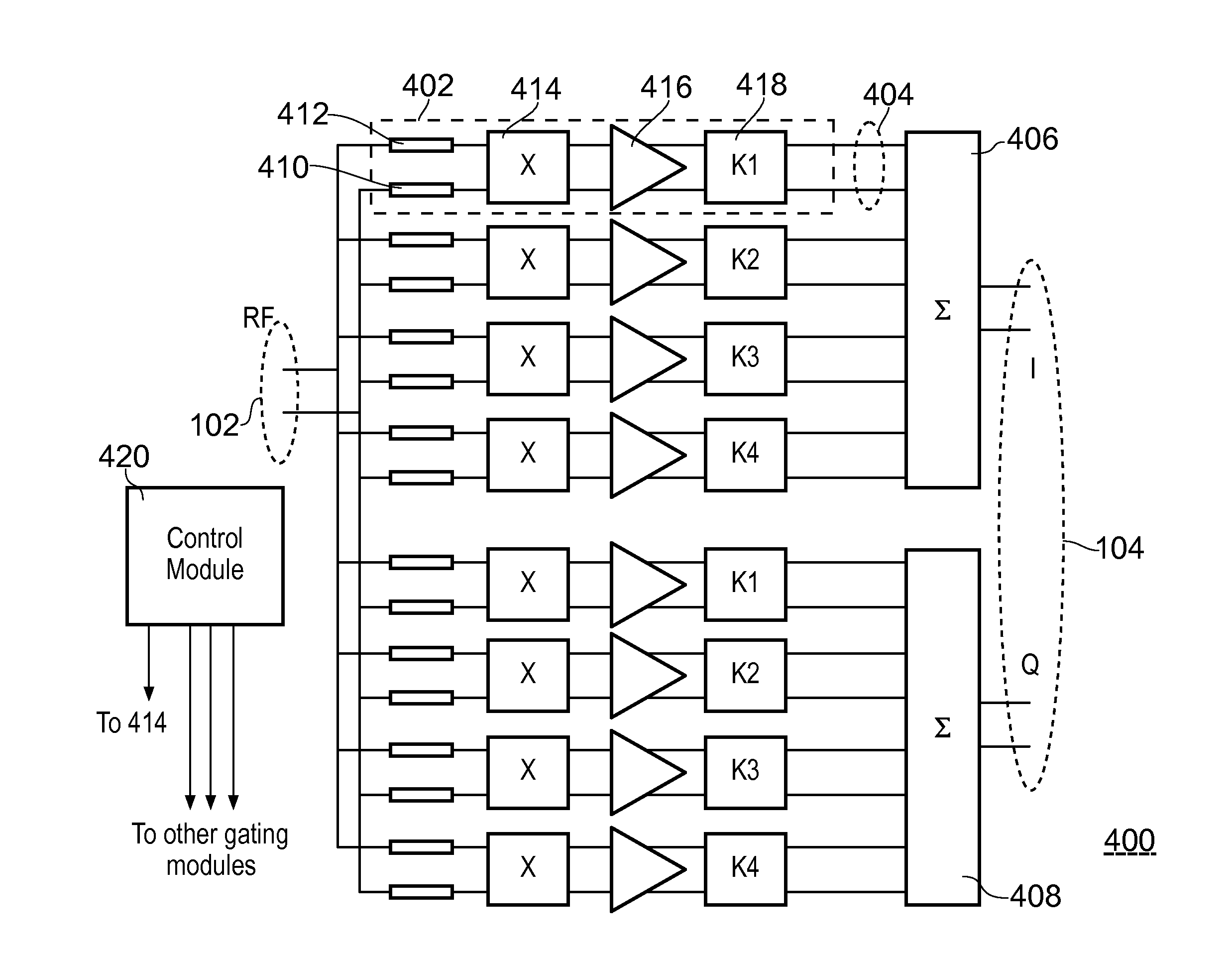
[0021]FIG. 4 is a diagram of a passive HR mixer 400 according to the invention. Mixer 400 has an input 102 receiving an RF input signal and an output 104 for supplying in-phase (I) and quadrature (Q) IF output signals. In the example shown, the input signal and output signal are differential signals. The “I” and “Q” signals together form a complex signal from which positive and negative spectral components can be separately extracted. In another example (not shown), only one of the signals “I” and “Q” are generated. The mixer 400 comprises multiple segments that are all of similar configuration connected to the input 102. In order to not obscure the drawing, only one of the segments has been labelled by reference numeral 402.
[0022]The configuration of the segments is now discussed with reference to segment 402, and is applicable to all segments. Segment 402 has a segment output 404 for supplying a weighted contribution to the differential output signals 104. For each output signal (...
second embodiment
[0032]A second embodiment will now be described with reference to FIGS. 9 and 10, which show diagrams of a further mixer 900. This embodiment improves on the conversion efficiency of the mixer 400, the mixer conversion efficiency being defined as the ratio between the power of the IF output signal and the power of the RF input signal. The mixer 900 uses segments in a similar arrangement to the mixer 400 of FIG. 4, however, the segments of the mixer 900 can each comprise multiple sub-mixing stages that are hereinafter referred to as “unit cells”. The unit cells are all substantially identical to one another, and each comprise one gating module and one respective IF amplifier.
[0033]Different segments have different numbers of unit cells. For example, the segment 902 in mixer 900 has 5 unit cells (indicated by the label “5x”), the segment next to it has 4 unit cells (indicated by the label “4x”), etc. As most of the weighting is now implemented in the RF domain by having different numb...
fourth embodiment
[0055]FIG. 12 shows a mixer 1200 and a signal diagram 1201 according to the invention. The mixer 1200 comprises eight segments, each segment indicated as having 1, 3, 4, or 5 unit cells. As with the previous embodiments, each unit cell comprises one gating module connected to one respective amplifier.
[0056]The eight segments each receive one of the control signals LO_1, LO_2, LO_3, LO_4, LO_5, LO_6, LO_7, and LO_8, and the control signal that a segment receives is used to control all the gating modules of the unit cells of that segment. The control signals LO_1-LO_8 are generated by a control module 1206, similar to the control module 420 of mixer 400. As can be seen on the timing diagram 1201, the waveforms of the control signals LO_1-LO_8 are all the same as one another (they are identical except for phase shifts).
[0057]An important difference between the gating modules of this embodiment and the gating modules of the previous embodiments, is that the gating modules of this embodi...
PUM
 Abstract
Description
Claims
Application Information